4x4 Rock Buggy TC 2.4 Build
 Moderator
 12-30-2015, 06:30 PM
#179
Junior Member
Thread Starter

After dong some research on turbo intakes I didn't feel like my original design provided enough plenum capacity. I am going to have to fit the entire piece of D-shaped plenum unmodified. I went back to the drawing board and determined that it just wasn't going to happen without cutting the oil filter housing off. So I devised one of the most ghetto-genius ways to blow air through the block and out the oil ports while I cut to prevent shavings from getting into the block. I practiced on my junk-engine and it appeared to have worked beautifully because afterwards I didn't see a single piece of aluminum-dust in any of them, they all had just perfectly clear oil residue. So I proceed onto my good engine.
I'll post some pics later. I'm sure ya'll are going to cringe.
I'll post some pics later. I'm sure ya'll are going to cringe.
Last edited by patooyee; 12-30-2015 at 06:38 PM.
12-30-2015, 11:19 PM
#181
Junior Member
Thread Starter
I figured out where all 3 ports lead in the oil filter housing. One drains to the oil pan via the back of the block. The other goes to the oil pump outlet and the other inlet. There are ports on the block exterior for all of these. I made some more ghetto block adapter fittings:

Both were 12mx1.75. One replaced my turbo oil feed fitting on the exhaust side of the block. The other replaced the oil pressure sensor on the intake side. The third port I used was just the crank case vent on the valve cover. Then I ghetto-rigged this abortion together to blow shop air into all 3 ports at once:

It was a large leak so it took many recharges of my shop compressor to get the job done. I didn't grind or cut if I didn't have air blowing through. Eventually the housing came off:

Some more grinding and contouring left me with this:

I will have this for sale in the classifieds here shortly as a result:

I'm aware that this isn't the best way to do this. ideally one should tear down to a bare block. I just couldn't justify the time and expense given the life expectancy requirements for the engine. I'll change my oil several times early on after the buggy is running and cut the filter open to see what's going on.
Still unfinished, but here is my new plan for the manifold:

This gives me roughly 150% engine displacement capacity in the plenum. I'm going to see if I can run some simulations on flow characteristics in SW ...
Both were 12mx1.75. One replaced my turbo oil feed fitting on the exhaust side of the block. The other replaced the oil pressure sensor on the intake side. The third port I used was just the crank case vent on the valve cover. Then I ghetto-rigged this abortion together to blow shop air into all 3 ports at once:
It was a large leak so it took many recharges of my shop compressor to get the job done. I didn't grind or cut if I didn't have air blowing through. Eventually the housing came off:
Some more grinding and contouring left me with this:
I will have this for sale in the classifieds here shortly as a result:
I'm aware that this isn't the best way to do this. ideally one should tear down to a bare block. I just couldn't justify the time and expense given the life expectancy requirements for the engine. I'll change my oil several times early on after the buggy is running and cut the filter open to see what's going on.
Still unfinished, but here is my new plan for the manifold:
This gives me roughly 150% engine displacement capacity in the plenum. I'm going to see if I can run some simulations on flow characteristics in SW ...
 12-31-2015, 09:08 AM
#183
Junior Member
Thread Starter
http://friedrice.blogspot.com/2014/04/theory-maf-sensor-placement.html?m=1
12-31-2015, 12:29 PM
#184
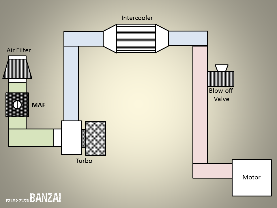
So with a recirculate you would use this image and run your recirc pipe from the bypass valve to between the MAF and turbo inlet. I feel the sensor being in this position is better for the life of the sensor since you won't have oil blow by from the turbo getting all over it. From my understanding it is easier to tune as well since the MAF can't read PSI only airflow. You can run it in the other position as well, just keep in mind that your IAT1 sensor is in the MAF.
The following users liked this post:
patooyee (12-31-2015)
12-31-2015, 01:06 PM
#185
Junior Member
Thread Starter
That sounds like a good suggestion and I think will actually work out better from a logistical fabrication of plumbing stand point in my setup.
I'm sorry if I am confusing the BOV / recirc valve terminology. When I google for recirc valves nothing turns up. To find them I have to search for BOV's that have outlets that will allow re-circulation plumbing. So I'm not really sure which term I should be using for the sake of this thread and am kind of using them interchangeably for lack of knowing otherwise.
I'm sorry if I am confusing the BOV / recirc valve terminology. When I google for recirc valves nothing turns up. To find them I have to search for BOV's that have outlets that will allow re-circulation plumbing. So I'm not really sure which term I should be using for the sake of this thread and am kind of using them interchangeably for lack of knowing otherwise.
12-31-2015, 02:41 PM
#186
I think the correct wording is turbo bypass valve, but even finding anything with those search terms in Google isn't great. Something like this is probably what you're looking for, even if it is a bit over kill. IMO the one I posted about earlier that was ~$30 will work fine for your application. You're going to be running less than 15psi right?
12-31-2015, 03:03 PM
#189
I use bpv/bov pretty interchangably. It doesnt really matter. I guess technically a bpv recircs and a bov is vta. Do what ^he said just recirc it back after the maf. Doesnt really matter the amount of boost as long as youre using a quality valve. Also, the le5 doesnt have iat2, only iat1. If you want to see iat2, you have to pull that wire from the maf sensor and use an lsj or lnf TMAP sensor. It will still read as iat1 in the computer though so make sure your tables are set up for that.
12-31-2015, 03:05 PM
#190
Junior Member
Thread Starter
I'd like to find one that uses v-band clamps or at least flanges ... I know I'm being picky now.
01-02-2016, 01:53 PM
#195
Junior Member
Thread Starter
BNF returned my PM but only answered half my questions. I guess its the holiday season but its frustrating to wait a week to get a return and then only get half the questions answered. I'm waiting again to hear back about whether I need a restrictor in my oil supply line now. But he did say that -6 was too small for the drain, need -10. So I re-did the drain line fittings today. Still waiting on fittings to make the hose. This will need to be a soft hose as I don't have a die to bend -10 hard line. :-\


01-02-2016, 04:36 PM
#197
Junior Member
Thread Starter
01-02-2016, 04:45 PM
#200
Junior Member
Thread Starter
Come to think of it, there's not really a great place to put it higher in the pan. Everywhere else is inaccessible or in the way, which is why I put it where I did. I'll probably go around the back of the block to the lower right port in this pic:
That drains directly to the pan IIRC. Does that sound OK?
That drains directly to the pan IIRC. Does that sound OK?