HPtuners Cam Phasing Help
 10-03-2014, 01:31 PM
#1
New Member
Thread Starter

Join Date: 05-15-13
Location: Edmonton
Posts: 37
Likes: 0
Received 0 Likes
on
0 Posts
HPtuners Cam Phasing Help
Hi Guys,
I'm having trouble understanding the cam phasing table in HPtuners. This is what the stock tables for the LNF look like:
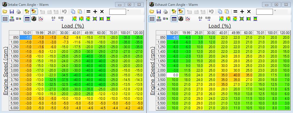
Now HPtuners, as far as I can tell, doesn't tell you what direction of cam phasing is positive or negative. I can't tell if positive or negative is advance or retard of the cam signals. I did some searching here and on the HP tuners forums but couldn't find an answer. The HPtuners LNF guide and a number of other threads I looked at didn't say this information either.
Also I'm not wanting to tune the cam phasing table to get more power or anything like that. I'm wanting to change the table so that I can start figuring out how the camshaft pulses relate to the TDC of the different cylinders. And how the signals change with camshaft phasing. Essentially I'm still trying to answer the questions I posed in this thread here that received no replies. https://www.cobaltss.net/forums/2-0l...l-help-312874/
Also I seem to notice that changing cam values in the idle table does not cause the cam phasing to change. I read that another poster in another thread was also saying that it seems that changes to the cam idle table do not work. However no one else corroborated this so I was wondering if anyone else could shed some insight on that.
In summary.
I'm having trouble understanding the cam phasing table in HPtuners. This is what the stock tables for the LNF look like:
Now HPtuners, as far as I can tell, doesn't tell you what direction of cam phasing is positive or negative. I can't tell if positive or negative is advance or retard of the cam signals. I did some searching here and on the HP tuners forums but couldn't find an answer. The HPtuners LNF guide and a number of other threads I looked at didn't say this information either.
Also I'm not wanting to tune the cam phasing table to get more power or anything like that. I'm wanting to change the table so that I can start figuring out how the camshaft pulses relate to the TDC of the different cylinders. And how the signals change with camshaft phasing. Essentially I'm still trying to answer the questions I posed in this thread here that received no replies. https://www.cobaltss.net/forums/2-0l...l-help-312874/
Also I seem to notice that changing cam values in the idle table does not cause the cam phasing to change. I read that another poster in another thread was also saying that it seems that changes to the cam idle table do not work. However no one else corroborated this so I was wondering if anyone else could shed some insight on that.
In summary.
- What corresponding direction of camshaft phasing to the positive and negative values in the table correspond to. Advance or retard?
- Does changing the cam phasing in the idle table have any effect?
 10-03-2014, 03:19 PM
#2
Senior Member

The idle tables definitely have an effect. If you disable cat heating but leave the cold idle cam angles stock the idle is a tad choppy. If you adjust the cold cam idle angles to the same as the warm idle tables the idle smooths out. Whether the scanner records the change or not I am not sure as things like drivability are not recorded by the scanner well.
As far as the cam angles relation to degrees before TDC or after TDC as far as I know no one has decoded the exact numbers. The units in hp tuners appear to be in 10ths of a degree because you can go plus or minus 256 units.
As far as the cam angles relation to degrees before TDC or after TDC as far as I know no one has decoded the exact numbers. The units in hp tuners appear to be in 10ths of a degree because you can go plus or minus 256 units.
10-03-2014, 04:04 PM
#3
New Member

I've read a LOT of threads on HP tuners about this, and i think I got it, although my interpretation is different than anybody else's.
1) Exhaust cam phaser only "retards" the exhaust cam.
2) Intake cam phaser only "advances" the intake cam.
3) Exhaust cam is "parked" during warm idle, which has a value of "-6" in HPtuners, and if you read the Exhaust cam sensor pid, it will read "0", as in 0 degrees moved from parked.
4) Intake cam is "parked" during warm idle, which has a value of "10" in HPTuners, and if you read the intake cam sensor PID, it will read "0", as in 0 degrees actuated from their parked position.
5) the values are in "crank degrees" (value is twice as big as "cam degrees"), and it is with respect to Top Dead Center (TDC) as Terminator2 said. so negative values mean moving advanced than "parked", before TDC, positive values mean more retarded than "parked"
I cannot understand why "parked" or "not actuated" is -6 for exhaust, and 10 for intake in HPtuners editor, but it does line up with the sensor PID reads that they have in the scanner.
Basically the cams are at the "least overlap" when they are both parked, and any movement will only add overlap.
So in the 50% load, 3k rpm area, it has the most overlap, exhaust cam is retarded a lot, intake cam is advanced a lot, most overlap, people seem to think this was done for fuel economy and "exhaust gas recirculation" effect.
the cam tables in HPtuners DEFINITELY affect the cams at idle, and the cam sensor PIDs, you just have to manipulate the right table, and there are a lot of them, Cat idle cold, cat idle warm, cat main cold, cat main warm, idle cold, idle warm, main cold, main warm. Just because you turned off "cat heating" doesn't mean that it stops using the Cat heating cam phaser tables, I can actually prove the opposite.
Remember though that cam phasors are moved by oil pressure, and oil pressure is lower at idle, so i think that if you try to push it, you might find the limit eventually, at idle.
Let me know if any of this is unclear, i can try to explain it better.
I am hoping terminator2 or someone could can correct me if any of this is wrong.
10-03-2014, 05:20 PM
#4
New Member
Thread Starter
Join Date: 05-15-13
Location: Edmonton
Posts: 37
Likes: 0
Received 0 Likes
on
0 Posts
Thanks so much for the replies. It seems the problem is more complicated than I thought. That is weird that HP tuners would program as 1/10th of a degree crank angle. I might try to contact HP tuners to see if I can get a specific answer on them for that value.
ForceFedDork, that information about parked values and the discrepancy between the PIDs and the actual value is starting to make sense. Thanks for explaining that.
If I wanted to set my valves so they behaved like an extremely vanilla and simple engine would I just set all those idle tables to 0? Like for example I wanted exhaust valve to close at TDC of the exhaust stroke and intake valve to open at TDC of the intake stroke.
10-03-2014, 06:07 PM
#5
New Member
hi MasterOfApplience
I'm gonna take some heat for this but i do not agree with the majority here; everyone thinks that the values in the editor are 1/10th of a degree.
I think that each integer is directly proportional to 1 crank degree; 1-to-1 ratio.
What i was saying earlier is that if you want your cams to stay parked all the time , then put all values to -6 for exhaust and 10 for intake. (not that i would recommend this, your car will run poorly with that much lobe separation; the engine was designed with expectation that the cam phasers will reduce the lobe separation / increase overlap.)
When it comes to relating the cam phasing values in the editor to the physical position of the cam phasers i am still struggling with that relationship.
if you google "lnf cam specs" the second link is a pdf of the cam specs. See if you can make sense of that.
Now here things get really sketchy:
It says that the exhaust cam valve timing is -120 deg, i assume that is the peak of the cam lobe, and duration of 194 deg. so -120+(194/2)= -23 deg, that would be the "closing of the exhaust cam". Lets assume that this is with respect to the "parked" position, therefore you would have to set the HPtuners tables to 23-6? = 17??? But that is only true if you assume 1mm lash is what you call "open" on the cams. I don't have any other data point to call "open"Again, i dont understand where this -6 and 10 values come from.
It doesn't seem like either of us know enough to fully understand cam phasing, so don't get tied up trying to open/close valves at TDC, but rather keep track of relative changes compared to parked or stock values.
Lastly; dont get tied up to the fact that you can type in a value of +/- 256 in the editor. That only means that the data type is 9 bits long value, 2^9th = 512, this goes back to programming. Is it really a coincidence that it fits so perfectly to +/- 8bit resolution? that seems like a programmers thinking to me. I bet that if you put in a value such as 150 in those tables, you will find the maximum limit of adjustment of the cam phaser, you could see this by the fact that the cam sensor PID will saturate at a value lower than 150. I have never tried this because I am very fond of my LNF, this is all just an assumption.
10-04-2014, 10:29 AM
#6
Senior Member
I've read a LOT of threads on HP tuners about this, and i think I got it, although my interpretation is different than anybody else's.
1) Exhaust cam phaser only "retards" the exhaust cam.
2) Intake cam phaser only "advances" the intake cam.
3) Exhaust cam is "parked" during warm idle, which has a value of "-6" in HPtuners, and if you read the Exhaust cam sensor pid, it will read "0", as in 0 degrees moved from parked.
4) Intake cam is "parked" during warm idle, which has a value of "10" in HPTuners, and if you read the intake cam sensor PID, it will read "0", as in 0 degrees actuated from their parked position.
5) the values are in "crank degrees" (value is twice as big as "cam degrees"), and it is with respect to Top Dead Center (TDC) as Terminator2 said. so negative values mean moving advanced than "parked", before TDC, positive values mean more retarded than "parked"
I cannot understand why "parked" or "not actuated" is -6 for exhaust, and 10 for intake in HPtuners editor, but it does line up with the sensor PID reads that they have in the scanner.
Basically the cams are at the "least overlap" when they are both parked, and any movement will only add overlap.
So in the 50% load, 3k rpm area, it has the most overlap, exhaust cam is retarded a lot, intake cam is advanced a lot, most overlap, people seem to think this was done for fuel economy and "exhaust gas recirculation" effect.
the cam tables in HPtuners DEFINITELY affect the cams at idle, and the cam sensor PIDs, you just have to manipulate the right table, and there are a lot of them, Cat idle cold, cat idle warm, cat main cold, cat main warm, idle cold, idle warm, main cold, main warm. Just because you turned off "cat heating" doesn't mean that it stops using the Cat heating cam phaser tables, I can actually prove the opposite.
Remember though that cam phasors are moved by oil pressure, and oil pressure is lower at idle, so i think that if you try to push it, you might find the limit eventually, at idle.
Let me know if any of this is unclear, i can try to explain it better.
I am hoping terminator2 or someone could can correct me if any of this is wrong.
1) Exhaust cam phaser only "retards" the exhaust cam.
2) Intake cam phaser only "advances" the intake cam.
3) Exhaust cam is "parked" during warm idle, which has a value of "-6" in HPtuners, and if you read the Exhaust cam sensor pid, it will read "0", as in 0 degrees moved from parked.
4) Intake cam is "parked" during warm idle, which has a value of "10" in HPTuners, and if you read the intake cam sensor PID, it will read "0", as in 0 degrees actuated from their parked position.
5) the values are in "crank degrees" (value is twice as big as "cam degrees"), and it is with respect to Top Dead Center (TDC) as Terminator2 said. so negative values mean moving advanced than "parked", before TDC, positive values mean more retarded than "parked"
I cannot understand why "parked" or "not actuated" is -6 for exhaust, and 10 for intake in HPtuners editor, but it does line up with the sensor PID reads that they have in the scanner.
Basically the cams are at the "least overlap" when they are both parked, and any movement will only add overlap.
So in the 50% load, 3k rpm area, it has the most overlap, exhaust cam is retarded a lot, intake cam is advanced a lot, most overlap, people seem to think this was done for fuel economy and "exhaust gas recirculation" effect.
the cam tables in HPtuners DEFINITELY affect the cams at idle, and the cam sensor PIDs, you just have to manipulate the right table, and there are a lot of them, Cat idle cold, cat idle warm, cat main cold, cat main warm, idle cold, idle warm, main cold, main warm. Just because you turned off "cat heating" doesn't mean that it stops using the Cat heating cam phaser tables, I can actually prove the opposite.
Remember though that cam phasors are moved by oil pressure, and oil pressure is lower at idle, so i think that if you try to push it, you might find the limit eventually, at idle.
Let me know if any of this is unclear, i can try to explain it better.
I am hoping terminator2 or someone could can correct me if any of this is wrong.
 10-06-2014, 10:47 AM
#8
Former Vendor

I have posted about this before after we monitored cam position on my lab scope and compared it to crank position. The tables are in fact scaled in crank degrees.
The reason that the intake cam tables start at 10 and move backwards are based on the open point of the intake valves at 10 degrees atdc when fully retarded.
The reason that the exhaust cam tables start at -6 and move forward are based on the closing point of the exhaust valves at 6 degrees btdc when fully advanced.
This means that if you set both cams to 0 in the charts, then you have 0 overlap because the exhaust valves are just getting closed and the intake valves are just starting to open right at top dead center.
Last edited by Matt M; 10-06-2014 at 04:06 PM.
10-07-2014, 09:34 AM
#9
New Member
wow, Matt M, thanks a lot for clearing all that up.
I think all the questions about how they work have been answered.
Now about tuning for performance and/or fuel economy, that's a different story.
Any chance anyone figured out how to tune cam phasing so that it doesn't drop off after 5k rpm?
Looking at all the logs it seems like it looses volumetric efficiency pretty bad past 5k rpm.
10-07-2014, 09:49 AM
#10
Senior Member
wow, Matt M, thanks a lot for clearing all that up.
I think all the questions about how they work have been answered.
Now about tuning for performance and/or fuel economy, that's a different story.
Any chance anyone figured out how to tune cam phasing so that it doesn't drop off after 5k rpm?
Looking at all the logs it seems like it looses volumetric efficiency pretty bad past 5k rpm.
I think all the questions about how they work have been answered.
Now about tuning for performance and/or fuel economy, that's a different story.
Any chance anyone figured out how to tune cam phasing so that it doesn't drop off after 5k rpm?
Looking at all the logs it seems like it looses volumetric efficiency pretty bad past 5k rpm.
10-07-2014, 10:34 AM
#11
Former Vendor
wow, Matt M, thanks a lot for clearing all that up.
I think all the questions about how they work have been answered.
Now about tuning for performance and/or fuel economy, that's a different story.
Any chance anyone figured out how to tune cam phasing so that it doesn't drop off after 5k rpm?
Looking at all the logs it seems like it looses volumetric efficiency pretty bad past 5k rpm.
I think all the questions about how they work have been answered.
Now about tuning for performance and/or fuel economy, that's a different story.
Any chance anyone figured out how to tune cam phasing so that it doesn't drop off after 5k rpm?
Looking at all the logs it seems like it looses volumetric efficiency pretty bad past 5k rpm.
10-07-2014, 12:41 PM
#12
New Member
Thread Starter
Join Date: 05-15-13
Location: Edmonton
Posts: 37
Likes: 0
Received 0 Likes
on
0 Posts
Do you guys know if spark timing is just as complicated? or is the spark timings table directly correlated to degrees after TDC. That might be easier for me to figure out the correct injection positions that way, and then deal with the cam pulses later. I'm going to collect some spark data for all the cylinders now and I'll post it here in a few hours or so.
10-07-2014, 01:20 PM
#13
New Member
Hello Matt M,
What I meant by volumetric efficiency decreasing past 5k rpm is that: if i keep constant boost (21psi), fairly constant IAT2, while doing an RPM sweep, i notice that "airload" pid, and the custom g/cyl calculation both start decreasing. Although MAF air flow is not decreasing, it is plateauing, as rpm increases. I think if VE would be constant, MAF would increase with increase in RPM.
I thought this means that the volumetric efficiency is dropping, and even though the car is still making good power, (if i make the assumption that MAF air flow is directly proportional to hp, yes, large assumption, i know) that would mean that the car has a very flat HP curve.
I understand i am probably "overclocking" the turbo in high RPM, probably a little outside of it's efficiency island, causing hotter air, etc.
My car is: 2008 cobalt, 85k miles, upper charge pipe, catless DP, drop in k&n filter, 3bar sensors, stock turbo; Tune is 21psi, stock cam tables, stock spark tables, <-- im new to tuning taking it slowly on 93 octane.
All i was asking is if there is a way to offset some of the VE drop by playing with the cam phasers.
Since i have you're guy's attention i'm gonna tread jack for a second, i got clutch slip a little in 5th, at 2500 or 2700 rpm at 21 psi, stock cams, stock spark. Is this normal? or is it due to worn out clutch at 85k miles?
MasterOfApplience,
I think spark timing is a lot easier. it is based in crank degrees, but it is BEFORE TDC. So high positive values is spark before TDC, seems common on all literature with all other engines i've read about. 3 details worth noting: 1) there are 4 "main spark" tables, which are dependent on cam phaser location, you can figure out what i mean by that, for your lab testing, you could set them all to the same values to remove a uncertainty. 2) There are tables that add/subract to the main spark tables that are based on Engine cooling temp (ECT) and Intake air temp (IAT). I'm sure you can figure out what i mean, ex: if air is very hot, more prone to pre-detonation, then the IAT table has negative values in it, so it will remove a few degrees of timing from the Main spark advance tables to try to avoid knock.
3) at idle "optimum spark table" seem to get involved, this is more about torque management, lots of opinions on this, i'll keep mine to myself. if you care, read the thread about it on HP tuners forum, the username of the writer was something like "gmtech4xxx" something.
a necessary "Thank You" to Terminator2 and Matt M for putting up with my noob comments and questions on here; thanks again.
Last edited by ForceFedDork; 10-07-2014 at 01:34 PM.
10-07-2014, 01:33 PM
#14
Senior Member
Hello Matt M,
What I meant by volumetric efficiency decreasing past 5k rpm is that: if i keep constant boost (21psi), fairly constant IAT2, while doing an RPM sweep, i notice that "airload" pid, and the custom g/cyl calculation both start decreasing. Although MAF air flow is not decreasing, it is plateauing, as rpm increases. I think if VE would be constant, MAF would increase with increase in RPM.
I thought this means that the volumetric efficiency is dropping, and even though the car is still making good power, (if i make the assumption that MAF air flow is directly proportional to hp, yes, large assumption, i know) that would mean that the car has a very flat HP curve.
I understand i am probably "overclocking" the turbo in high RPM, probably a little outside of it's efficiency island, causing hotter air, etc.
My car is: 2008 cobalt, 85k miles, upper charge pipe, catless DP, drop in k&n filter; Tune is 21psi, stock cam tables, stock spark tables, <-- im new to tuning taking it slowly on 93 octane.
All i was asking is if there is a way to offset some of the VE drop by playing with the cam phasers.
MasterOfApplience,
I think spark timing is a lot easier. it is based in crank degrees, but it is BEFORE TDC. So high positive values is spark before TDC, seems common on all literature with all other engines i've read about. 3 details worth noting: 1) there are 4 "main spark" tables, which are dependent on cam phaser location, you can figure out what i mean by that, for your lab testing, you could set them all to the same values to remove a uncertainty. 2) There are tables that add/subract to the main spark tables that are based on Engine cooling temp (ECT) and Intake air temp (IAT). I'm sure you can figure out what i mean, ex: if air is very hot, more prone to pre-detonation, then the IAT table has negative values in it, so it will remove a few degrees of timing from the Main spark advance tables to try to avoid knock.
3) at idle "optimum spark table" seem to get involved, this is more about torque management, lots of opinions on this, i'll keep mine to myself. if you care, read the thread about it on HP tuners forum, the username of the writer was something like "gmtech4xxx" something.
a necessary "Thank You" to Terminator2 and Matt M for putting up with my noob comments and questions on here; thanks again.
10-07-2014, 06:25 PM
#15
New Member
Thread Starter
Join Date: 05-15-13
Location: Edmonton
Posts: 37
Likes: 0
Received 0 Likes
on
0 Posts
Here is the data that I collected. At least this gives me some starting point of what camshaft pulses correspond to what cylinder. I was running at idle and roughly displaying 4.5 degrees of spark advance for all the cases. Because I only have a 4 CH oscilloscope I recorded CKP, exhaust cam, and IC1 every time and swapped out IC2, IC3, and IC4 for each case and made a composite for this picture.
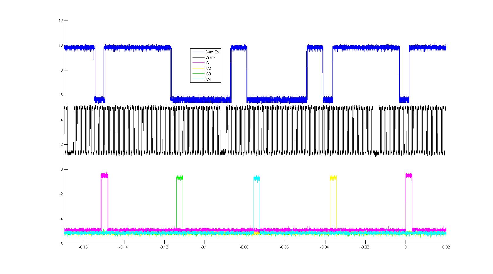
It seems to me like every spark signal has a corresponding cam shaft falling edge that is the same as it. The thing that confuses me is if you read the quote from the shop manual in my original post, is that the two cams are phased, even when VCM scanner says 0. This is due to that parked postion. But it makes the quote in the shop manual no longer true. Also I wonder which cam pulse the engine controller uses.
It seems to me like every spark signal has a corresponding cam shaft falling edge that is the same as it. The thing that confuses me is if you read the quote from the shop manual in my original post, is that the two cams are phased, even when VCM scanner says 0. This is due to that parked postion. But it makes the quote in the shop manual no longer true. Also I wonder which cam pulse the engine controller uses.
10-07-2014, 09:52 PM
#16
New Member
MasterOfApplience,
Looks like 60-2 crank sensor wheel (60 teeth, 2 missing), so 6 crank degrees per pulse.
I agree that there appears to be a connection to exhaust cam falling edge.
However i think that spark is linked to the falling edge of ur signals? I think the coil gets "charged during the pulse, i read some people call it dwell" and the actual spark is on the falling edge.
Counting crank pulses i can't figure out a correlation to the actual edges, my only assumption is that there are offsets from both crank sensor and cam sensors, and the edges are not actualy TDC?
Matt M, Terminator2
First time posting an image on a forum, so odds are it won't work right.
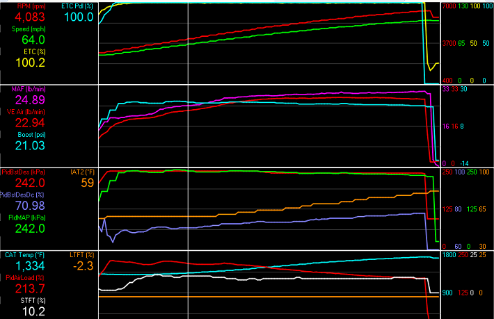
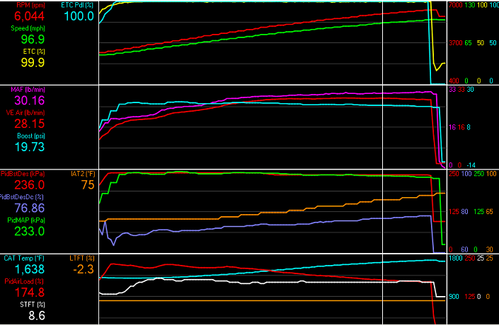
a) Looking back at this log i can't see a knee at 5k rpm like i thought i did, it must have been my boost control in the last tune i tried. So my previous comment doesn't make sense, i realize that now.
b) The boost desired PID drops off at 5k rpm because of my turbo "pressure ratio" value, I did it on purpose trying to protect the turbo? probably unjustified?
c) This is the first time i looked at WG DC PID, but it looks like im losing another psi at 6k rpm that i could probably fix with either the PID controller or probably the Duty Cycle Corr Table?
d) I accidentally edited my post after Terminator already replied, any input on the clutch comment? I'm gonna tread jack for a second, i got clutch slip a little in 5th, at 2500 or 2700 rpm at 21 psi, stock cams, stock spark. Is this normal? or is it due to worn out clutch at 85k miles? Any input is greatly appreciated.
Thanks guys.
Looks like 60-2 crank sensor wheel (60 teeth, 2 missing), so 6 crank degrees per pulse.
I agree that there appears to be a connection to exhaust cam falling edge.
However i think that spark is linked to the falling edge of ur signals? I think the coil gets "charged during the pulse, i read some people call it dwell" and the actual spark is on the falling edge.
Counting crank pulses i can't figure out a correlation to the actual edges, my only assumption is that there are offsets from both crank sensor and cam sensors, and the edges are not actualy TDC?
Matt M, Terminator2
First time posting an image on a forum, so odds are it won't work right.
a) Looking back at this log i can't see a knee at 5k rpm like i thought i did, it must have been my boost control in the last tune i tried. So my previous comment doesn't make sense, i realize that now.
b) The boost desired PID drops off at 5k rpm because of my turbo "pressure ratio" value, I did it on purpose trying to protect the turbo? probably unjustified?
c) This is the first time i looked at WG DC PID, but it looks like im losing another psi at 6k rpm that i could probably fix with either the PID controller or probably the Duty Cycle Corr Table?
d) I accidentally edited my post after Terminator already replied, any input on the clutch comment? I'm gonna tread jack for a second, i got clutch slip a little in 5th, at 2500 or 2700 rpm at 21 psi, stock cams, stock spark. Is this normal? or is it due to worn out clutch at 85k miles? Any input is greatly appreciated.
Thanks guys.
Last edited by ForceFedDork; 10-08-2014 at 05:55 PM.
10-08-2014, 09:48 AM
#17
Former Vendor
Hello Matt M,
What I meant by volumetric efficiency decreasing past 5k rpm is that: if i keep constant boost (21psi), fairly constant IAT2, while doing an RPM sweep, i notice that "airload" pid, and the custom g/cyl calculation both start decreasing. Although MAF air flow is not decreasing, it is plateauing, as rpm increases. I think if VE would be constant, MAF would increase with increase in RPM.
I thought this means that the volumetric efficiency is dropping, and even though the car is still making good power, (if i make the assumption that MAF air flow is directly proportional to hp, yes, large assumption, i know) that would mean that the car has a very flat HP curve.
I understand i am probably "overclocking" the turbo in high RPM, probably a little outside of it's efficiency island, causing hotter air, etc.
My car is: 2008 cobalt, 85k miles, upper charge pipe, catless DP, drop in k&n filter, 3bar sensors, stock turbo; Tune is 21psi, stock cam tables, stock spark tables, <-- im new to tuning taking it slowly on 93 octane.
All i was asking is if there is a way to offset some of the VE drop by playing with the cam phasers.
Since i have you're guy's attention i'm gonna tread jack for a second, i got clutch slip a little in 5th, at 2500 or 2700 rpm at 21 psi, stock cams, stock spark. Is this normal? or is it due to worn out clutch at 85k miles?
MasterOfApplience,
I think spark timing is a lot easier. it is based in crank degrees, but it is BEFORE TDC. So high positive values is spark before TDC, seems common on all literature with all other engines i've read about. 3 details worth noting: 1) there are 4 "main spark" tables, which are dependent on cam phaser location, you can figure out what i mean by that, for your lab testing, you could set them all to the same values to remove a uncertainty. 2) There are tables that add/subract to the main spark tables that are based on Engine cooling temp (ECT) and Intake air temp (IAT). I'm sure you can figure out what i mean, ex: if air is very hot, more prone to pre-detonation, then the IAT table has negative values in it, so it will remove a few degrees of timing from the Main spark advance tables to try to avoid knock.
3) at idle "optimum spark table" seem to get involved, this is more about torque management, lots of opinions on this, i'll keep mine to myself. if you care, read the thread about it on HP tuners forum, the username of the writer was something like "gmtech4xxx" something.
a necessary "Thank You" to Terminator2 and Matt M for putting up with my noob comments and questions on here; thanks again.
There is very little to be gained in top end power with the cam tables. The factory tables are very close to optimum for the stock turbo. There is a little to be found, but the LNF ECM was set up pretty well to begin with in that regard.
Most people ramp in the boost to peak at later rpms when running the stock clutch. It's pretty easy to make it slip, otherwise.
10-08-2014, 09:54 AM
#18
Former Vendor
Here is the data that I collected. At least this gives me some starting point of what camshaft pulses correspond to what cylinder. I was running at idle and roughly displaying 4.5 degrees of spark advance for all the cases. Because I only have a 4 CH oscilloscope I recorded CKP, exhaust cam, and IC1 every time and swapped out IC2, IC3, and IC4 for each case and made a composite for this picture.
It seems to me like every spark signal has a corresponding cam shaft falling edge that is the same as it. The thing that confuses me is if you read the quote from the shop manual in my original post, is that the two cams are phased, even when VCM scanner says 0. This is due to that parked postion. But it makes the quote in the shop manual no longer true. Also I wonder which cam pulse the engine controller uses.
It seems to me like every spark signal has a corresponding cam shaft falling edge that is the same as it. The thing that confuses me is if you read the quote from the shop manual in my original post, is that the two cams are phased, even when VCM scanner says 0. This is due to that parked postion. But it makes the quote in the shop manual no longer true. Also I wonder which cam pulse the engine controller uses.
10-08-2014, 08:59 PM
#19
Senior Member
MasterOfApplience,
Looks like 60-2 crank sensor wheel (60 teeth, 2 missing), so 6 crank degrees per pulse.
I agree that there appears to be a connection to exhaust cam falling edge.
However i think that spark is linked to the falling edge of ur signals? I think the coil gets "charged during the pulse, i read some people call it dwell" and the actual spark is on the falling edge.
Counting crank pulses i can't figure out a correlation to the actual edges, my only assumption is that there are offsets from both crank sensor and cam sensors, and the edges are not actualy TDC?
Matt M, Terminator2
First time posting an image on a forum, so odds are it won't work right.
Attachment 6390
Attachment 6391
a) Looking back at this log i can't see a knee at 5k rpm like i thought i did, it must have been my boost control in the last tune i tried. So my previous comment doesn't make sense, i realize that now.
b) The boost desired PID drops off at 5k rpm because of my turbo "pressure ratio" value, I did it on purpose trying to protect the turbo? probably unjustified?
c) This is the first time i looked at WG DC PID, but it looks like im losing another psi at 6k rpm that i could probably fix with either the PID controller or probably the Duty Cycle Corr Table?
d) I accidentally edited my post after Terminator already replied, any input on the clutch comment? I'm gonna tread jack for a second, i got clutch slip a little in 5th, at 2500 or 2700 rpm at 21 psi, stock cams, stock spark. Is this normal? or is it due to worn out clutch at 85k miles? Any input is greatly appreciated.
Thanks guys.
10-08-2014, 09:06 PM
#20
Senior Member
It's nice to see someone else using a scope to map out engine management events. Most people go at it blind and then just talk about "pluses and minuses" or "bigger numbers and smaller numbers" without actually understanding what is taking place when they make adjustments.
10-10-2014, 03:30 PM
#21
New Member
Thread Starter
Join Date: 05-15-13
Location: Edmonton
Posts: 37
Likes: 0
Received 0 Likes
on
0 Posts
MasterOfApplience,
Looks like 60-2 crank sensor wheel (60 teeth, 2 missing), so 6 crank degrees per pulse.
I agree that there appears to be a connection to exhaust cam falling edge.
However i think that spark is linked to the falling edge of ur signals? I think the coil gets "charged during the pulse, i read some people call it dwell" and the actual spark is on the falling edge.
Counting crank pulses i can't figure out a correlation to the actual edges, my only assumption is that there are offsets from both crank sensor and cam sensors, and the edges are not actualy TDC?
I found that the spark is linked to the falling edge of the IC signals. I did this by running the engine at different speeds. The gap between the rising edge and the falling edge was always a specific time, not a set number of crank shaft teeth. The falling edge was always consistent to comparisons made at different RPM but same ignition timing but the rising edge was not.
10-10-2014, 04:01 PM
#22
New Member
Thread Starter
Join Date: 05-15-13
Location: Edmonton
Posts: 37
Likes: 0
Received 0 Likes
on
0 Posts
10-13-2014, 03:09 PM
#23
Former Vendor
You don't need to spend a lot of money to understand what is taking place when you make changes in the tables. Just take the time to familiarize and learn what each chart is specifically adjusting. Once you have, it will only get easier when you move on to a new platform.

Thread
Thread Starter
Forum
Replies
Last Post