When you click on links to various merchants on this site and make a purchase, this can result in this site earning a commission. Affiliate programs and affiliations include, but are not limited to, the eBay Partner Network.
the pcv does function under boost as the system reverses direction and the intake manifold becomes the fresh air source the pcv valve turns into a restrictor allowing x amount of air to bypass under wot but not having the tube hooked up to the air intake creates pressure in the crank case and in general most modern engines use low tension top rings and standard tension oil rings and a vacuum pump will move more air then relying the engine to do it itself that's why when run correctly they remove more contaminates from the system
Last edited by mrbelvedere; 09-12-2017 at 08:16 AM.
For the record I modified my phenolic spacer so that the stock LSJ PCV system would work with my L61 head.
This is a follow up question for stumpalump. Why couldn't you run a vacuum pump with a breather filter on the valve cover to allow in fresh air so it is setup more like the stock system? I'm just asking because to me it seems you could setup a standalone system to work just like or even better than the stock system because the ventilation could be consistent vs. fluctuating with manifold vacuum.
the pcv does function under boost as the system reverses direction and the intake manifold becomes the fresh air source the pcv valve turns into a restrictor allowing x amount of air to bypass under wot but not having the tube hooked up to the air intake creates pressure in the crank case and in general most modern engines use low tension top rings and standard tension oil rings
So that isn't a a full check valve? I tested one when it was outside the car and it seemed to me that the valve would only flow air if the manifold pressure was lower than the crankcase pressure. Under boost I would think this criteria to not be met unless the crankcase pressure exceeds boost levels which you wouldn't think would happen with an open line to the intake from the valve cover as excess pressure should be expelled through that tube. Let me know where I am going wrong because I would like to fully understand our PCV system. I thought I did but now I'm doubting.
So that isn't a a full check valve? I tested one when it was outside the car and it seemed to me that the valve would only flow air if the manifold pressure was lower than the crankcase pressure. Under boost I would think this criteria to not be met unless the crankcase pressure exceeds boost levels which you wouldn't think would happen with an open line to the intake from the valve cover as excess pressure should be expelled through that tube. Let me know where I am going wrong because I would like to fully understand our PCV system. I thought I did but now I'm doubting.
no not a full check valve its a 2 way valve to meter air
if you push air on the manifold side its shut off but if there is a vacuum on the manifold side(cruise or part throttle) air moves through it from the head now when you put vacuum on the head (WOT) side from the tube on the back of the valve cover air moves through it but its metered air if air from the intake manifold but was not able to be pulled through at wot the dipstick would never stay in place and the rings would be unseated due to excessive case pressure
For the record I modified my phenolic spacer so that the stock LSJ PCV system would work with my L61 head.
This is a follow up question for stumpalump. Why couldn't you run a vacuum pump with a breather filter on the valve cover to allow in fresh air so it is setup more like the stock system? I'm just asking because to me it seems you could setup a standalone system to work just like or even better than the stock system because the ventilation could be consistent vs. fluctuating with manifold vacuum.
Nobody does but you could. The idea of a pump is not to just relieve pressure but to put the crankcase under constant vacuum. After learning what a cluster the stock PCV is I wonder if a pump would not work very well on an LSJ in the AC compressor or tensioner location. More weight vs a few hp. More complex vs stupid simple. This is all out race stuff but since dabbling in that is what we do..... Tech: How External Vacuum Pumps Free Up Horsepower - EngineLabs
I also channeled the PCV system from my LE5 to work with the LSJ manifold. I started with a clear hose to monitor any blow-by to my CAI as I just cleaned the Laminova cores to like new condition and did not want to cake them with oil. That hose today still has not collected anything in it but I am only at 10PSI of boost.
If your young or have never worked on early 1900's vehicles you may want to ready where the PCV system came from. Vehicles used to have a draft tube that was cut at a 45 degree angle so a slight vacuum was created to help draw vapors out of the engine when the vehicle went down the road.
Are these shitty diagrams I threw together accurate or where am I off?
All engines have blow by so it is a constant movement of air back and forth on a properly operating PCV system. Take your oil cap off and hold a piece of paper over the filler hole. You should see the paper pulse against and away from the filler hole. During high boost situations the crankcase can become more positive than atmospheric as there is no engine vacuum at WOT but once returning to idle the crankcase will vent back out. The major issue is when there is never any ventilation. Older engine with rope main seals required a properly working PCV system or oil would literally run off the seal.
there is one other method you can use for crankcase evacuation, something that plays on the same theory as a road draft tube, and thats a header evac kit. a tube is placed in the collector at a 45 degree angle to the exhaust flow, and it hooks to your valve cover. the kits come with a valve to prevent exhaust gas from backflowing into the crankcase. these kits work quite well, they were actually a staple in many forms of racing before vacuum pumps were a thing
there is one other method you can use for crankcase evacuation, something that plays on the same theory as a road draft tube, and thats a header evac kit. a tube is placed in the collector at a 45 degree angle to the exhaust flow, and it hooks to your valve cover. the kits come with a valve to prevent exhaust gas from backflowing into the crankcase. these kits work quite well, they were actually a staple in many forms of racing before vacuum pumps were a thing
The concept was first introduced by Bill Million at Hedman Hedders and initially developed on the engine dynos at both Edelbrock and Traco Engineering. Traco-powered Penske Trans Am Camaros were among the first cars to run it in competition.
A Pan-Evac system connects the valve covers on both sides of the engine to the exhaust header collectors with one-way check valves and vent tubes that blend into the exhaust stream at approximately 45 degrees. Exiting exhaust gasses pull a vacuum on the tubes, thus drawing excess crankcase pressure from the sump and discharging it out the collector. This action relieves blow-by pressure under the rings, reducing windage and contamination. Although purely passive, the system proved remarkably efficient, and thousands of racers used them religiously until the emergence of modern external vacuum pumps.
Your components need to be connected to make better sense.
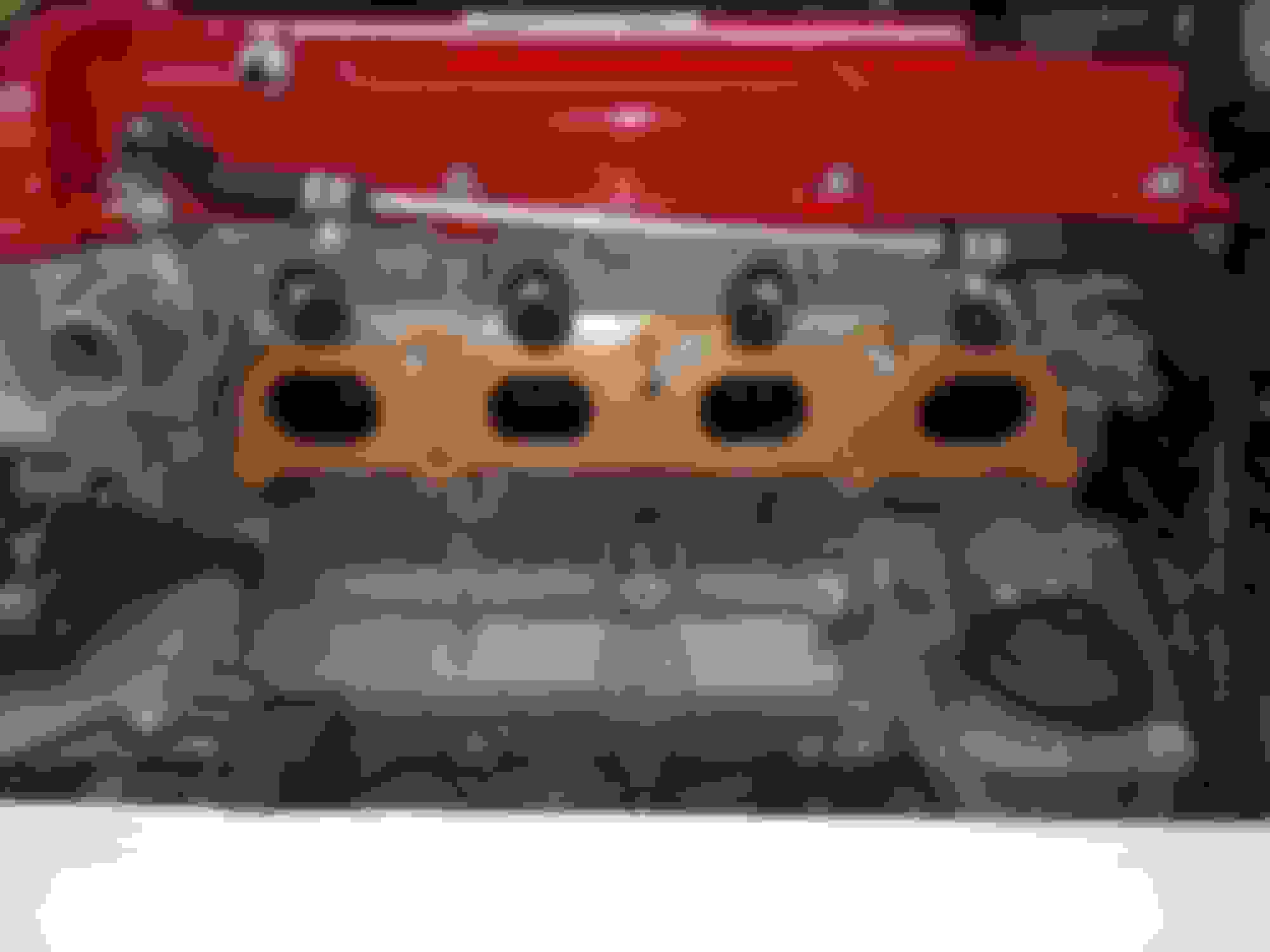
This is a 2009 2.2 PCV system from GM
They are connected with lines with arrows indicating air flow as I wasn't going to waste time with isometric drawings. This drawing here has the same routing as my drawing labeled "vacuum" so that is confirmed. But how does it behave under boost?
With stock manifold, boost will fill the crankcase. With lsj mani, the check valve closes.
That's what I thought. So under boost the pcv valve is closed and the valve cover is venting excess pressure to the intake tract with no fresh air being introduced to the crankcase. So according to you my horribly drawn diagrams are accurate. Thanks,
Can I assume that no fresh air enters the crankcase? In other words is the only port to the outside the bung on the valve cover? The oil cap appears to be sealed.
Can I assume that no fresh air enters the crankcase? In other words is the only port to the outside the bung on the valve cover? The oil cap appears to be sealed.
Fresh air enters through that bung on the valve cover. If you have it plugged and oil cap on then there is no inlet for fresh air.
All engines have blow by so it is a constant movement of air back and forth on a properly operating PCV system. Take your oil cap off and hold a piece of paper over the filler hole. You should see the paper pulse against and away from the filler hole. During high boost situations the crankcase can become more positive than atmospheric as there is no engine vacuum at WOT but once returning to idle the crankcase will vent back out. The major issue is when there is never any ventilation. Older engine with rope main seals required a properly working PCV system or oil would literally run off the seal.
at wot vacuum is generated in another place to pull vacuum on the crank case
Originally Posted by Slowbalt2000
With stock manifold, boost will fill the crankcase. With lsj mani, the check valve closes.
no it does not it is open in both directions all it does is meter air in both directions
 09-12-2017, 08:04 AM


 Moderator

