2.0 LNF Engine: How To - Add the analogue boost gauge on a factory RPD car
 04-27-2011, 12:26 AM
#1
Member
Thread Starter
Join Date: 12-02-09
Location: Toronto
Posts: 296
Likes: 0
Received 0 Likes
on
0 Posts
How To - Add the analogue boost gauge on a factory RPD car
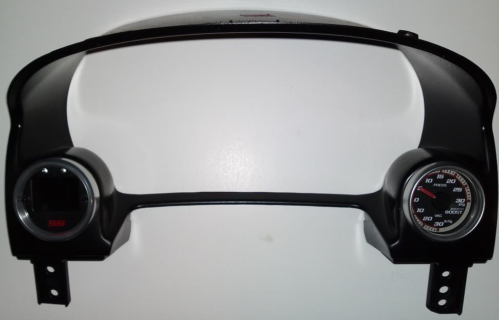
Here is how to add the OEM factory boost gauge to a car that came with an RPD. I'll only explain how to add it since I kept my RPD and put the gauge into a dual cluster bezel.
1. Get the following:
Analogue boost gauge, GM part # 25800715

Connector for boost gauge (this is very common for other connections in the car like power mirrors and trunk release button, you can reuse one of those from a wreck easily or buy the parts listed from a place like mouser.com)
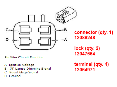
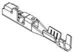
Female terminal for X201, GM part # 12191812 (ask for service tray 19 at the parts desk)
2. Disconnect the negative battery cable.
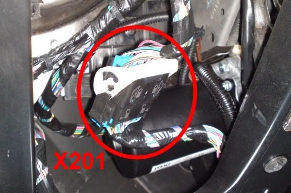
3. Locate connector X201 under the dash, just below the instrument cluster. you only need to remove the lower trim panel beneath the steering wheel.
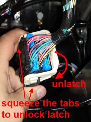
4. Separate the connector halves
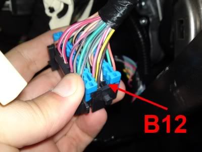
5. Locate position B12 on the female connector.
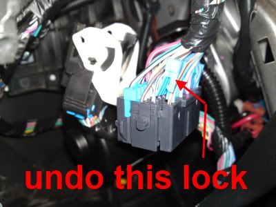
6. Disengage the secondary lock which acts as a backup to hold the terminals in place.
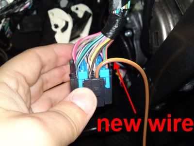
7. Attach a wire to the female terminal 12191812 and insert the terminal into position B12.
8. Reinsert the terminal lock into X201, reconnect the two halves together.
9. Complete the wiring for the new boost gauge connector, connecting to the sources specified.
Pin A - Ignition switched power source
Pin B - Instrument Panel lamp dimming signal
Pin C - To new wire from X201 - B12
Pin D - To Ground
10. Install boost gauge where you like and plug in the connector from step 9.
11. Re-attach negative battery terminal and enjoy a dedicated boost gauge to compliment your RPD!
1. Get the following:
Analogue boost gauge, GM part # 25800715
Connector for boost gauge (this is very common for other connections in the car like power mirrors and trunk release button, you can reuse one of those from a wreck easily or buy the parts listed from a place like mouser.com)
Female terminal for X201, GM part # 12191812 (ask for service tray 19 at the parts desk)
2. Disconnect the negative battery cable.
3. Locate connector X201 under the dash, just below the instrument cluster. you only need to remove the lower trim panel beneath the steering wheel.
4. Separate the connector halves
5. Locate position B12 on the female connector.
6. Disengage the secondary lock which acts as a backup to hold the terminals in place.
7. Attach a wire to the female terminal 12191812 and insert the terminal into position B12.
8. Reinsert the terminal lock into X201, reconnect the two halves together.
9. Complete the wiring for the new boost gauge connector, connecting to the sources specified.
Pin A - Ignition switched power source
Pin B - Instrument Panel lamp dimming signal
Pin C - To new wire from X201 - B12
Pin D - To Ground
10. Install boost gauge where you like and plug in the connector from step 9.
11. Re-attach negative battery terminal and enjoy a dedicated boost gauge to compliment your RPD!
Last edited by TommyP; 10-28-2011 at 09:08 PM.

 04-27-2011, 10:32 AM
#4
Platinum Member
Platinum Member
any gauge that interperates an electrical signal (via map sensor, pressure senser/sender, temp senser/sender, ect ect) into an analogue signal isn't technically an analogue gauge.. just saying because the title is a little deceptive
Definitely a good write up though none the less..
Definitely a good write up though none the less..
04-27-2011, 11:10 AM
#5
Senior Member

wow, didnt know it was actually a electronic gauge. i thought it was an actual mechanical unit... good to know... and also WTF didnt they show vaccum on the RPD?!
04-27-2011, 01:49 PM
#6
Senior Member

Join Date: 08-23-09
Location: USA
Posts: 1,813
Likes: 0
Received 0 Likes
on
0 Posts
ya not having vacum sucks.
Also, didnt realize it was this easy *or so it looks* to add the boost gauge, maybe mount it on the steering column or something
edit: where did you splice into for ignition / cluster dimming...
Also, didnt realize it was this easy *or so it looks* to add the boost gauge, maybe mount it on the steering column or something
edit: where did you splice into for ignition / cluster dimming...
 04-27-2011, 10:10 PM
#8
Member
Thread Starter
Join Date: 12-02-09
Location: Toronto
Posts: 296
Likes: 0
Received 0 Likes
on
0 Posts
I literally just tested this two days ago but I took it apart to clean it up for the final install (gotta shorten some wires, add the Interceptor and route everything nicely). I also noticed that the RPD seemed slower then the gauge so i want to set the two side by side and make a vid to compare them. Two kids under 2 and a 10-12 hour a day job don't leave me with a lot of free time to spend in the garage lately.  I hope that this weekend I'll be able to do some more work on this. When I finish the install I'll post proper pics of my setup.
I hope that this weekend I'll be able to do some more work on this. When I finish the install I'll post proper pics of my setup.
05-11-2011, 10:25 PM
#9
Member
Thread Starter
Join Date: 12-02-09
Location: Toronto
Posts: 296
Likes: 0
Received 0 Likes
on
0 Posts
I finally got some time to do the side by side comparison I wanted to. lol It looks like the needles are matching pretty well the same info with no lag between them. I posted the video to Photobucket, link is below.
RPD vs Boost Gauge
RPD vs Boost Gauge
 06-12-2011, 10:34 PM
#12
Member
Thread Starter
Join Date: 12-02-09
Location: Toronto
Posts: 296
Likes: 0
Received 0 Likes
on
0 Posts
Because for some reason GM thought that Canadian  cars should get pressure readings in kpa instead of bar or psi. It is metric but nobody knows what kpa is. But I do know what degrees C is and not F for temperature. Unfortunatly it is not possible to mix metric and imperial units so this is the best solution plus I prefer to have a dedicated gauge.
cars should get pressure readings in kpa instead of bar or psi. It is metric but nobody knows what kpa is. But I do know what degrees C is and not F for temperature. Unfortunatly it is not possible to mix metric and imperial units so this is the best solution plus I prefer to have a dedicated gauge.
06-26-2011, 11:45 AM
#13
Senior Member
iTrader: (1)
Join Date: 08-23-07
Location: Haymarket/Norfolk Virginia
Posts: 3,940
Likes: 0
Received 0 Likes
on
0 Posts
what did you use to make that cluster? i have one that i need to redo but im not sure what would be best to use since i bought it from someone
Last edited by occsdude; 06-26-2011 at 12:07 PM.
 06-27-2011, 11:03 PM
#15
Member
Thread Starter
Join Date: 12-02-09
Location: Toronto
Posts: 296
Likes: 0
Received 0 Likes
on
0 Posts
I took a pic the other day of it installed, not the best pic because the sun is bright and on the drivers side in the morning, hence the reflection on the Interceptor.
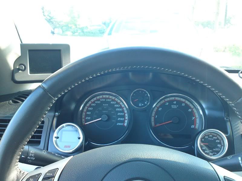
And thanks for the compliments. I'm not really in the business of making them but I will post the same How-To I wrote for the OCC forum here as well.
And thanks for the compliments. I'm not really in the business of making them but I will post the same How-To I wrote for the OCC forum here as well.

 06-28-2011, 10:18 PM
#18
Member
Thread Starter
Join Date: 12-02-09
Location: Toronto
Posts: 296
Likes: 0
Received 0 Likes
on
0 Posts
I wrote a How-To on making the bezel. I'm not really interested in making more but I'm willing to share how I did it so others can make their own.
Interior How To: Make a Dual Gauge Cluster Bezel - Cobalt SS Network
Interior How To: Make a Dual Gauge Cluster Bezel - Cobalt SS Network
10-28-2011, 06:46 PM
#19
Member
iTrader: (1)

Join Date: 08-13-07
Location: lakeland
Posts: 209
Likes: 0
Received 0 Likes
on
0 Posts
I just got done doing this and upon rev my needle goes up, not really boosting, but just sit reving. I looked to make sure it is in b12. any idea's? Is american different? On the otherside of the connector is I believe a tan wire. But I ran just like how you did through the connector. Any info would be appreciated.
10-28-2011, 07:46 PM
#20
New Member

Join Date: 02-13-10
Location: Pittsburgh
Posts: 115
Likes: 0
Received 0 Likes
on
0 Posts
you wont get boost if you are not in gear putting a load on the engine, but you will drop to zero vacuum if you stab the gas while just sitting there
does that help?
does that help?
10-28-2011, 09:04 PM
#22
Member
Thread Starter
Join Date: 12-02-09
Location: Toronto
Posts: 296
Likes: 0
Received 0 Likes
on
0 Posts
I highly doubt that there is any difference. For the 200 odd Cobalt SS's per year they sold in Canada it wouldn't make sense. Probably you have a bad ground or power connection. Where did you get the ground and power wire from?
10-29-2011, 10:27 AM
#25
Member
iTrader: (1)
Join Date: 08-13-07
Location: lakeland
Posts: 209
Likes: 0
Received 0 Likes
on
0 Posts
I grounded just below the a pillar by the connector the metal I believe it is for the firewall un did the bolt and grounded there. Power ran to fuse box using the sunroof fuse.