Electrical: How-To: A/F Gauge Install on 2006 Cobalt LS & Supercharged
 07-24-2006, 08:52 PM
#1
Senior Member
Thread Starter
Join Date: 05-17-06
Location: Ft. Eustis, VA
Posts: 7,283
Likes: 0
Received 0 Likes
on
0 Posts
How-To: A/F Gauge Install on 2006 Cobalt LS & Supercharged
Vehicles covered by this write-up: 2005-2006 Cobalt LS & Supercharged
Installation Duration: 1 hour
Skills needed(1 being least and 10 being expert): 2
Parts you need to purchase:
Some sort of gauge pod(your preference)
Air/Fuel Gauge(Summit Racing brand Part # SUM-G2986)
Wire
Crimps
Tools:
Clothes hanger
Wire cutters and strippers
Crimpers
10mm socket & wrench
Directions:
1) Disconnect battery(located in trunk)
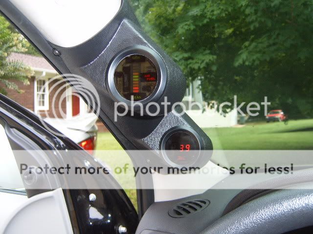
2) Install gauge pod onto A-pillar or whereever following their instructions. I used a a-pillar gauge pod and had to attach it with four screws and drill a hole for the wires as I'm going more for function right now.
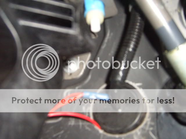
3) Remove rubber plug on firewall located as shown. Slide clothes hanger through hole and find in the engine bay. Attach two wires to it and pull back through. This is your power wire and A/F signal wire. Mark them to keep them seperated.
4) Hooking up the power wire - using a crimp put the red A/F wire(power) and crimp it into one side. The power wire you ran through the firewall will be connected to the other side using the same method.
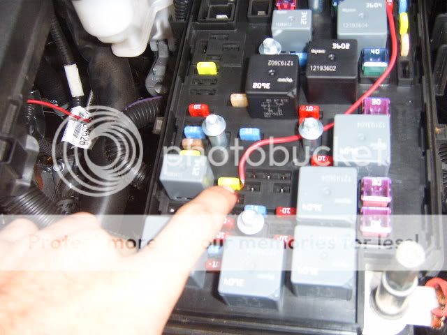
5) Now adding power - Take off the fuse box cover and find the IP Ign fuse. A mini green 20A fuse. Strip off some of the wire and put this on ONE side of the fuse and re-insert fuse. Congrats-You have power now.
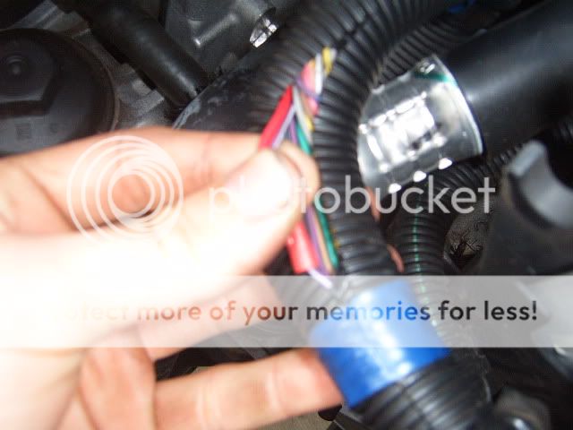
6) Hooking up the signal wire(grey wire) - Perform the same method as connecting the wires as you did the power. Locating the signal wire is fairly easy. In the bundle of wires next to the ECU locate the Purple wire with a white strip. Cut this wire and strip the ends. Connect the signal wire you ran through the firewall on one wire and connect the two using a crimp.
Location of bundle:
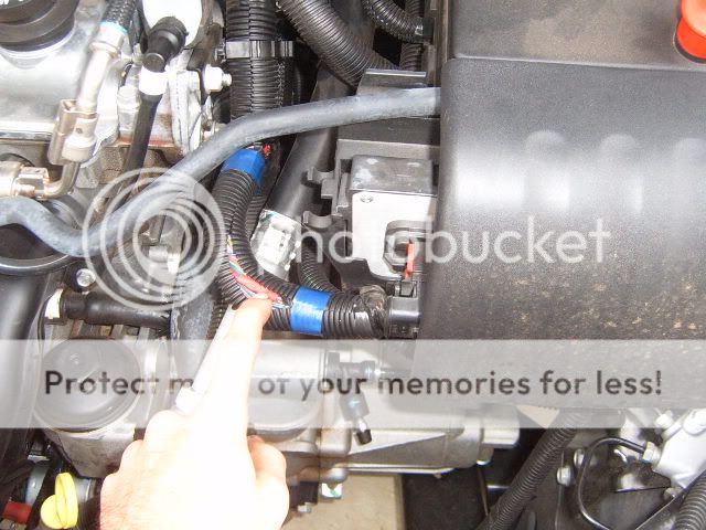
Wire:
7) Hooking up your ground - Anywhere will be great, but I used the metal bracket that supports my clutch pedal. Just removed one bolt put the black wire there and bolted it back down.
8: Reconnect battery and check wires and make sure everythings snug.
9) Crank her up and watch the gauge. Give it a second to get the signal and tap the gas a couple times to see if the gauge changes. After a few minutes of idle it may dance which is normal.
10) If everything is working properly you are finished!
Disclaimer: Do not put gauge where it will affect your night time driving. I am under no reason responsible for where you install it. Please drive safely & responsible.
Installation Duration: 1 hour
Skills needed(1 being least and 10 being expert): 2
Parts you need to purchase:
Some sort of gauge pod(your preference)
Air/Fuel Gauge(Summit Racing brand Part # SUM-G2986)
Wire
Crimps
Tools:
Clothes hanger
Wire cutters and strippers
Crimpers
10mm socket & wrench
Directions:
1) Disconnect battery(located in trunk)
2) Install gauge pod onto A-pillar or whereever following their instructions. I used a a-pillar gauge pod and had to attach it with four screws and drill a hole for the wires as I'm going more for function right now.
3) Remove rubber plug on firewall located as shown. Slide clothes hanger through hole and find in the engine bay. Attach two wires to it and pull back through. This is your power wire and A/F signal wire. Mark them to keep them seperated.
4) Hooking up the power wire - using a crimp put the red A/F wire(power) and crimp it into one side. The power wire you ran through the firewall will be connected to the other side using the same method.
5) Now adding power - Take off the fuse box cover and find the IP Ign fuse. A mini green 20A fuse. Strip off some of the wire and put this on ONE side of the fuse and re-insert fuse. Congrats-You have power now.
6) Hooking up the signal wire(grey wire) - Perform the same method as connecting the wires as you did the power. Locating the signal wire is fairly easy. In the bundle of wires next to the ECU locate the Purple wire with a white strip. Cut this wire and strip the ends. Connect the signal wire you ran through the firewall on one wire and connect the two using a crimp.
Location of bundle:
Wire:
7) Hooking up your ground - Anywhere will be great, but I used the metal bracket that supports my clutch pedal. Just removed one bolt put the black wire there and bolted it back down.
8: Reconnect battery and check wires and make sure everythings snug.
9) Crank her up and watch the gauge. Give it a second to get the signal and tap the gas a couple times to see if the gauge changes. After a few minutes of idle it may dance which is normal.
10) If everything is working properly you are finished!
Disclaimer: Do not put gauge where it will affect your night time driving. I am under no reason responsible for where you install it. Please drive safely & responsible.
Last edited by TommyP; 10-06-2012 at 09:07 AM.


 07-26-2006, 07:40 AM
#4
Senior Member

does this gauge run air fuels from the computer? because unless it does then you signal is fake and you need a wideband  i want to buy a air fuel gauge asap if its that easy lol
07-26-2006, 01:04 PM
#5
That would be a narrowband setup, which is why there isn't any sensor being installed. To install a wideband, it's pretty much the same thing, except you don't tap into that purple wire. You would hook it up to the sensor. You/someone will need to install a place to install the sensor though. It says in the instructions how far from the header to put it, I forget at the moment.
07-26-2006, 01:18 PM
#6
Senior Member
Join Date: 03-03-06
Location: Pittsburgh, PA
Posts: 4,958
Likes: 0
Received 0 Likes
on
0 Posts
May want to throw in an add-a-fuse. Unless you test the circuit after removing the fuse you put the stripped wire to, you only have a 50/50 chance of running a fused circuit to the gauge. If the power wire that runs through the firewall rubs between the steel and rubber boot, bye bye cobalt.
07-26-2006, 01:33 PM
#7
Senior Member

Join Date: 11-15-05
Location: Newton Highlands, Massachusetts
Posts: 2,693
Likes: 0
Received 0 Likes
on
0 Posts
nice write up, thanks for taking the time to do it and provide good pics of everything. you'd definitely want to put a fuse in that power wire, within 18" from the source. also for the record, this shows a narrowband installation.
07-26-2006, 01:45 PM
#8
Senior Member
Join Date: 01-02-05
Location: Winnipeg, MB
Posts: 833
Likes: 0
Received 0 Likes
on
0 Posts
Originally Posted by cvenom2122
does this gauge run air fuels from the computer? because unless it does then you signal is fake and you need a wideband i want to buy a air fuel gauge asap if its that easy lol
From what I've read, the AEM UEGO and Innovate LC-1 widebands can actually use your primary o2 sensor location and relay your narrowband signal back to your wiring harness for you using an analog output. One less sensor to replace and no need to get a bung welded would be the main benefits of doing that, I guess.
07-26-2006, 03:01 PM
#9
Senior Member
Join Date: 03-03-06
Location: Pittsburgh, PA
Posts: 4,958
Likes: 0
Received 0 Likes
on
0 Posts
Originally Posted by zomghax
The signal isn't "fake", it's just kinda useless as far as tuning and more of a light show than anything.
From what I've read, the AEM UEGO and Innovate LC-1 widebands can actually use your primary o2 sensor location and relay your narrowband signal back to your wiring harness for you using an analog output. One less sensor to replace and no need to get a bung welded would be the main benefits of doing that, I guess.
From what I've read, the AEM UEGO and Innovate LC-1 widebands can actually use your primary o2 sensor location and relay your narrowband signal back to your wiring harness for you using an analog output. One less sensor to replace and no need to get a bung welded would be the main benefits of doing that, I guess.
07-26-2006, 03:08 PM
#10
Senior Member
Join Date: 03-03-06
Location: Pittsburgh, PA
Posts: 4,958
Likes: 0
Received 0 Likes
on
0 Posts
A quick google search shows that AEM UEGO can emulate your stock rear O2 sensor by adjusting the output from 0-5v to 0-1v. zomghax, you sir, are the &^%$ing man. 
07-26-2006, 03:11 PM
#11
Senior Member
Join Date: 01-02-05
Location: Winnipeg, MB
Posts: 833
Likes: 0
Received 0 Likes
on
0 Posts
Originally Posted by Witt
Oh wow, I never thought about that. FedEx is delivering my AEM UEGO today. Do you have any more info on using an analog output to power the narrow band? Thanks greatly in advance.
http://www.hptuners.com/forum/showthread.php?t=2947
A bit of info on the AEM gauge confirming it works the same way, nothing too specific though:
http://www.hptuners.com/forum/showthread.php?t=6606
07-26-2006, 03:15 PM
#12
Senior Member
Join Date: 01-02-05
Location: Winnipeg, MB
Posts: 833
Likes: 0
Received 0 Likes
on
0 Posts
Originally Posted by Witt
A quick google search shows that AEM UEGO can emulate your stock rear O2 sensor by adjusting the output from 0-5v to 0-1v. zomghax, you sir, are the &^%$ing man.
 07-26-2006, 03:23 PM
#13
Senior Member
Join Date: 03-03-06
Location: Pittsburgh, PA
Posts: 4,958
Likes: 0
Received 0 Likes
on
0 Posts
Originally Posted by zomghax
My friends warned me against using it in the rear location because the cat will throw the wideband readings off. That seems to be the general consensus on the HPTuners forums as well. And thanks but I'm just a n00b who's trying to learn like everyone else
Some other forums that I googled mentioned the capacitor, but it might only be for older models of the UEGO or may have to do with the make/model of vehicle. Hopefully I'll know shortly.
07-26-2006, 03:39 PM
#14
Senior Member
Join Date: 01-02-05
Location: Winnipeg, MB
Posts: 833
Likes: 0
Received 0 Likes
on
0 Posts
Originally Posted by Witt
Yeah I read the same about the rear location, however I "think" if you use it in the front location, it has to be wired with a capacitor. Not sure, but if the FedEx guy ever gets here, I'll know for sure.
Some other forums that I googled mentioned the capacitor, but it might only be for older models of the UEGO or may have to do with the make/model of vehicle. Hopefully I'll know shortly.
Some other forums that I googled mentioned the capacitor, but it might only be for older models of the UEGO or may have to do with the make/model of vehicle. Hopefully I'll know shortly.
07-26-2006, 08:19 PM
#16
Senior Member
Thread Starter
Join Date: 05-17-06
Location: Ft. Eustis, VA
Posts: 7,283
Likes: 0
Received 0 Likes
on
0 Posts
Man wish this got the attention back when I was TRYING to find that purple wire. LOL
Circuit will be tested to make sure its fused. I don't want to run straight to the battery due to I don't want it lite up 24/7. So right now its just tied into that fuse. But I'll test the fuse tonight. I believe I have it on the right side, but gotta double check.
Circuit will be tested to make sure its fused. I don't want to run straight to the battery due to I don't want it lite up 24/7. So right now its just tied into that fuse. But I'll test the fuse tonight. I believe I have it on the right side, but gotta double check.
07-27-2006, 02:56 AM
#17
Senior Member
Join Date: 03-03-06
Location: Pittsburgh, PA
Posts: 4,958
Likes: 0
Received 0 Likes
on
0 Posts
Originally Posted by Blackout06LS
Man wish this got the attention back when I was TRYING to find that purple wire. LOL
07-27-2006, 07:21 AM
#18
Senior Member
Thread Starter
Join Date: 05-17-06
Location: Ft. Eustis, VA
Posts: 7,283
Likes: 0
Received 0 Likes
on
0 Posts
Originally Posted by Witt
haha, isn't that the way it always works?
07-27-2006, 06:19 PM
#20
Senior Member
Thread Starter
Join Date: 05-17-06
Location: Ft. Eustis, VA
Posts: 7,283
Likes: 0
Received 0 Likes
on
0 Posts
Originally Posted by cvenom2122
so are you actully getting real readings or is the gauge jumping up and down?
Just for everyone to know. I checked the fuse and it is correctly ran. The wire is NOT on the hot side it is indeed on the fused side.
Do you guys need a video of it to better understand how it functions?


 09-20-2006, 09:32 PM
#25
Senior Member

Join Date: 08-05-06
Location: long island
Posts: 1,552
Likes: 0
Received 0 Likes
on
0 Posts
ok so you use the purple wire.. here is my problem i cant seem to find my way into the engin bay through the fire wall.. will that same wire be found under the dash in the group of wires that link up to the plug for your ecm
?????
-drew
?????
-drew