
2.0 LSJ Engine: Install pics mechanical boost gauge , to go with ExHondaMans write up


Thread Starter
Senior Member
Joined: 07-03-05
Posts: 4,272
Likes: 0
From: South Bend , Indiana
Install pics mechanical boost gauge , to go with ExHondaMans write up
Here is ExHondaMan's write on how installed a mechanical boost gauge . Its excellent write up and tells you everything you need to know , but he said he didnt many pics , so I thought I'd post all my intstall pics to go with his thread .
ExHondaMan's write up
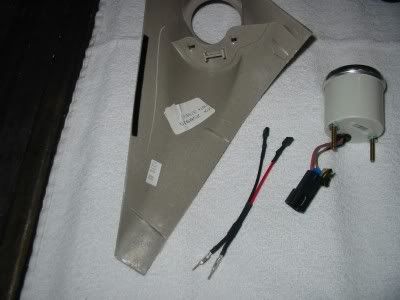
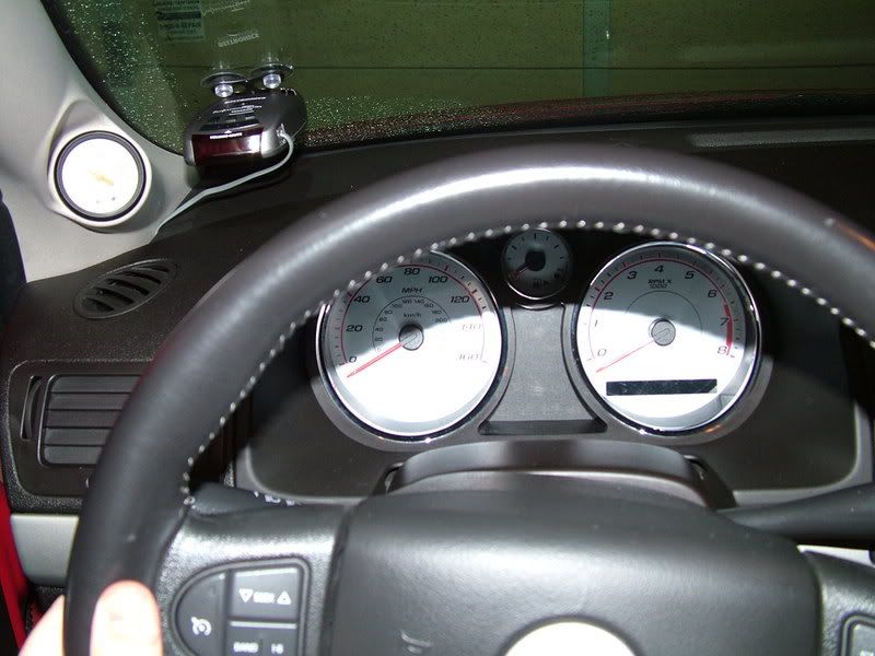
Heres the A-pillar , stock boost guage , and the harness I made for the lighting , so I didnt have to cut any stock wires . I ended up having the proper terminals at work to go into the stock boost guage connector .
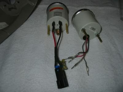
Heres the stock boost gauge next to the mechanical one . I only needed the postive and negative lighting wires . So I only used those cavity blocks in the stock connector on the autometer . Its easy to get the connector off the stock gauge without hurting the wires , all that holds the wire terminals in is a tab . New gauge is on the left with the stock harness connector adapted , stock gauge on the right with the connector removed from the wires .
This shows what u have to cut to make a autometer gauge work in the stock pillar

Here is the new gauge installed using Autometers black retainer bracket . When you go to install it it looks like theres no way in hell it will fit , but it does ....easily .
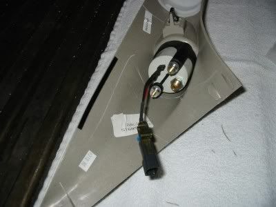
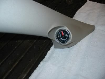
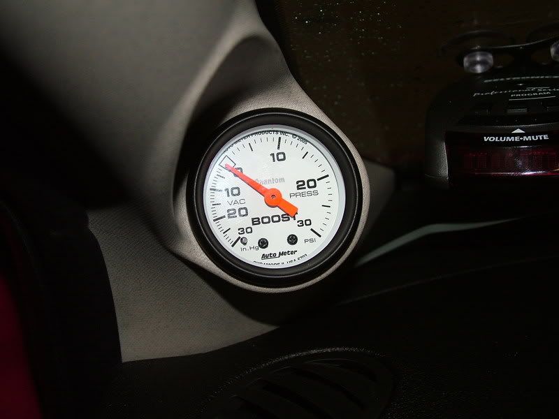
New gauge installed and ready to go it , with the vacum hose attached .
Front view
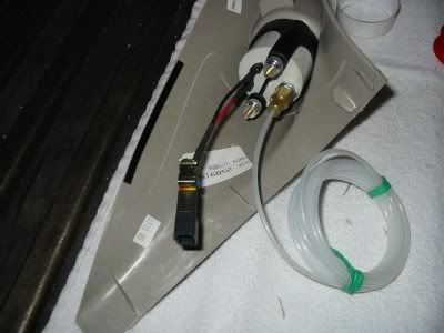
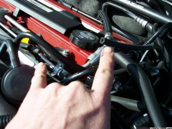
Heres a pic of the vacum line I used to T into for the gauge reading
Hopefully the pics help some with the ExHondaMans up write .
ExHondaMan's write up
Heres the A-pillar , stock boost guage , and the harness I made for the lighting , so I didnt have to cut any stock wires . I ended up having the proper terminals at work to go into the stock boost guage connector .
Heres the stock boost gauge next to the mechanical one . I only needed the postive and negative lighting wires . So I only used those cavity blocks in the stock connector on the autometer . Its easy to get the connector off the stock gauge without hurting the wires , all that holds the wire terminals in is a tab . New gauge is on the left with the stock harness connector adapted , stock gauge on the right with the connector removed from the wires .
This shows what u have to cut to make a autometer gauge work in the stock pillar
Here is the new gauge installed using Autometers black retainer bracket . When you go to install it it looks like theres no way in hell it will fit , but it does ....easily .
New gauge installed and ready to go it , with the vacum hose attached .
Front view
Heres a pic of the vacum line I used to T into for the gauge reading
Hopefully the pics help some with the ExHondaMans up write .


Junior Member
Joined: 05-31-05
Posts: 446
Likes: 0
From: Brick City, NJ
Nice write up!!!
1. Question I cant quit figure out what Tube did you T into, on the last pic??
Thanks,
Yes the car gotta be supercharged in order to have a stock Boost and Vac gauge....
No, the stock Gauge is Electric and gets its info from the Computer. The Mech Gauges are more correct.
1. Question I cant quit figure out what Tube did you T into, on the last pic??
Thanks,
Yes the car gotta be supercharged in order to have a stock Boost and Vac gauge....
Last edited by A-Town; Mar 13, 2007 at 08:54 PM. Reason: Automerged Doublepost

New Member
Joined: 01-21-07
Posts: 85
Likes: 2
From: united states
Nice write up!!!
1. Question I cant quit figure out what Tube did you T into, on the last pic??
Thanks,
Yes the car gotta be supercharged in order to have a stock Boost and Vac gauge....
No, the stock Gauge is Electric and gets its info from the Computer. The Mech Gauges are more correct.
1. Question I cant quit figure out what Tube did you T into, on the last pic??
Thanks,
Yes the car gotta be supercharged in order to have a stock Boost and Vac gauge....
No, the stock Gauge is Electric and gets its info from the Computer. The Mech Gauges are more correct.
Senior Member
Joined: 01-26-07
Posts: 2,155
Likes: 0
From: Colorado
no, sorry, I have a 2.2 so i dont know. But I'm trying to learn because im going to be putting a procharger on it. I'm in the process of figuring out the piping right now tho so were talking months down the line...
Thread Starter
Senior Member
Joined: 07-03-05
Posts: 4,272
Likes: 0
From: South Bend , Indiana
The line I teed into is the 1/4 vacum line that runs off the intake manifold and goes to the boost bypass . Take your injector cover plate off and youll see more clearly the line Im talking about .
Damn resurection , hhaha .
Damn resurection , hhaha .
Junior Member
Joined: 05-31-05
Posts: 446
Likes: 0
From: Brick City, NJ
Thank!! Now I know what it is, will be installed this weekend!!!

New Member
Joined: 01-21-07
Posts: 85
Likes: 2
From: united states
[QUOTE=SilverSS/SC;216855]Here is ExHondaMan's write on how installed a mechanical boost gauge . Its excellent write up and tells you everything you need to know , but he said he didnt many pics , so I thought I'd post all my intstall pics to go with his thread .
Heres a pic of the vacum line I used to T into for the gauge reading
dude i cannot find that hose to T into
Last edited by stvn; Mar 16, 2007 at 05:19 PM. Reason: Automerged Doublepost
Thread Starter
Senior Member
Joined: 07-03-05
Posts: 4,272
Likes: 0
From: South Bend , Indiana
Heres pics .
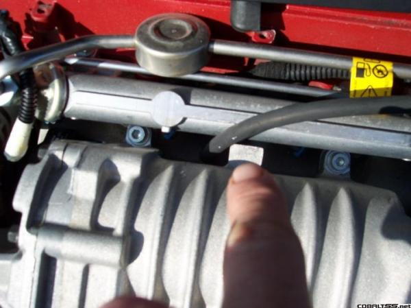
This is where the line begins . Its the ONLY vacum line coming out of the top pf the manifold .
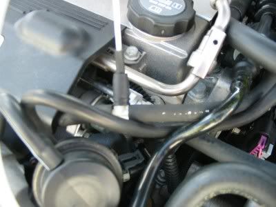
This is where that vacum line ends up at the boost bypass selonid .
https://www.cobaltss.net/gallery/files/2/4/3/5/bbm2.jpg
This is what it should look like if u have the bypass selonoid bypassed . I just used a vacum cap on end left open on the Tee .
This is where the line begins . Its the ONLY vacum line coming out of the top pf the manifold .
This is where that vacum line ends up at the boost bypass selonid .
https://www.cobaltss.net/gallery/files/2/4/3/5/bbm2.jpg
This is what it should look like if u have the bypass selonoid bypassed . I just used a vacum cap on end left open on the Tee .

Thread Starter
Senior Member
Joined: 07-03-05
Posts: 4,272
Likes: 0
From: South Bend , Indiana
New Member
Joined: 01-21-07
Posts: 85
Likes: 2
From: united states
im sorry i guess i didnt word it right. im asking if i can, add 2 more gauges. like an air/fuel and a voltmeter, but run the power wires of the 2 gauges to the power wire of the factory boost gauge power wire, so it will all be tied in to the factory dimmer swith. do you think it will work?

Thread Starter
Senior Member
Joined: 07-03-05
Posts: 4,272
Likes: 0
From: South Bend , Indiana
im sorry i guess i didnt word it right. im asking if i can, add 2 more gauges. like an air/fuel and a voltmeter, but run the power wires of the 2 gauges to the power wire of the factory boost gauge power wire, so it will all be tied in to the factory dimmer swith. do you think it will work?
Glad they helped 06 , that looks really good .
New Member
Joined: 01-21-07
Posts: 85
Likes: 2
From: united states
ok good. i was just makin sure i wouldnt blow a fuse or something. what are pigtails, ive never seen them?
