4x4 Rock Buggy TC 2.4 Build
 10-24-2015, 07:44 PM
#1
Junior Member
Thread Starter

4x4 Rock Buggy TC 2.4 Build
I'm building a 4x4 rock buggy using a drivetrain from a wrecked 2006 Cobalt SS 2.4. This build may take years and I may not post every pic as I don't know that ya'll will appreciate or care about them here. But some may find the Ecotec portion of the build interesting. I'm also kind of new / inexperienced in the 4-cylinder aftermarket. I come from background of V8 LS engines so I am hoping maybe people will give me insight as I move forward. Just some details for the build:
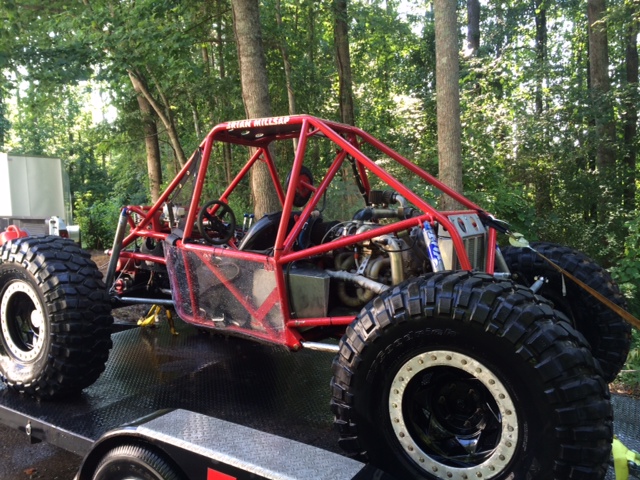
Full custom tube chassis
4 wheel steering Ford 9" axles
2.4 LE5
BNR GT2871R turbo
4t45e transaxle w/welded dif
40" sticky compound competition tires
17" Raceline aluminum beadlock wheels
This vehicle will not be street legal and will be towed from trail to trail.
This is what I started out with. The previous owner was out driving drunk after a party in the rain and ran it off the road, bounced it off of several trees. The floor boards were littered with red solo cups when I got it. Literally every body panel had some type of damage. He was lucky to live. He wasn't wearing a seatbelt and had 2 passengers. His head nailed the rear view mirror spearing it through the windshield to form a perfect bullet hole. He had a small scar on his forehead from it but was otherwise unharmed. The car had 75,000 miles on it and was owned by his grandmother until 68,000 miles so it only took the guy 7000 miles to total it. The car then sat outdoors in his grandmother's yard in a very rural AL town for a couple years while he had it for sale on Craig's List. During that time a critter found its way into the destroyed driver rear window and took up residence. During its tenure it shredded almost the entire interior until the owner got rid of it and tied up some chicken wire to keep it from coming back. Despite all the abuse, it still started and ran just fine which is all I cared about. I gave him $1000 for the car with title and drove it onto my trailer. It lived out the remainder of its life indoors at my shop until I tore it down for the drive train and a few other parts that I thought I might use later.


This is its final hour of life as I loaded it onto my trailer and took it off to the scrap yard where I got a whopping $214 in scrap value. Some may recognize it from the classifies section where I attempted to sell some of the parts cheap, even give many away. Surprisingly, I couldn't even give anything away as virtually everyone who expressed interest always just stopped responding to their own inquiries.

Full custom tube chassis
4 wheel steering Ford 9" axles
2.4 LE5
BNR GT2871R turbo
4t45e transaxle w/welded dif
40" sticky compound competition tires
17" Raceline aluminum beadlock wheels
This vehicle will not be street legal and will be towed from trail to trail.
This is what I started out with. The previous owner was out driving drunk after a party in the rain and ran it off the road, bounced it off of several trees. The floor boards were littered with red solo cups when I got it. Literally every body panel had some type of damage. He was lucky to live. He wasn't wearing a seatbelt and had 2 passengers. His head nailed the rear view mirror spearing it through the windshield to form a perfect bullet hole. He had a small scar on his forehead from it but was otherwise unharmed. The car had 75,000 miles on it and was owned by his grandmother until 68,000 miles so it only took the guy 7000 miles to total it. The car then sat outdoors in his grandmother's yard in a very rural AL town for a couple years while he had it for sale on Craig's List. During that time a critter found its way into the destroyed driver rear window and took up residence. During its tenure it shredded almost the entire interior until the owner got rid of it and tied up some chicken wire to keep it from coming back. Despite all the abuse, it still started and ran just fine which is all I cared about. I gave him $1000 for the car with title and drove it onto my trailer. It lived out the remainder of its life indoors at my shop until I tore it down for the drive train and a few other parts that I thought I might use later.
This is its final hour of life as I loaded it onto my trailer and took it off to the scrap yard where I got a whopping $214 in scrap value. Some may recognize it from the classifies section where I attempted to sell some of the parts cheap, even give many away. Surprisingly, I couldn't even give anything away as virtually everyone who expressed interest always just stopped responding to their own inquiries.
 10-24-2015, 07:57 PM
#2
Junior Member
Thread Starter
The life expectancy of an engine / trans in a rock buggy is very different than a daily driver. While they will assuredly be heavily abused, the actual total mileage they will have to endure the abuse for will be only a fraction of a normal drive train. The average rock buggy engine will probably see a total of a few thousand miles in its lifetime before it is rebuilt or torn out for something more powerful. So while the engine has 75,000 miles on it, even if I keep the rig for 10 years, it will probably only ever get to an actual 80,000 miles. However, given my history of owning only V8-powered rigs, I knew I would want more power out of the little Ecotec. I'm shooting for 350hp at the crank and I knew I would want to turbo charge it to get there. I didn't want to just boost a completely unknown engine though so I performed a compression check which revealed 110 - 120 psi in all cylinders. This was good news, right at spec according to the manual. I followed it up with a leak down test which revealed a max pressure loss of 3% at 75psi in any cylinder. The top end looks to be in good condition. I will check out the bottom end later when I pull the oil pan to TIG weld an oil return fitting into.
Here's the LNF coolant pipe on the LE5.

I've since received the LNF exhaust manifold and BNR turbo which I haven't taken pic of yet.
The first order of business in the transmission was to weld the differential. And since the dif is the last thing you pull out of the trans I went ahead and put new clutches in it at the same time. I intended to take pics of every step of the build process but my hands were always so greasy during it that I gave up on handling the camera / phone. Here is inside the cover with the valve body clutch support assembly removed:

That's about all the Ecotec-related pics I have at the moment. There will be more coming. Until then here is a pic of one of the tire/wheel combos:

Here's the LNF coolant pipe on the LE5.
I've since received the LNF exhaust manifold and BNR turbo which I haven't taken pic of yet.
The first order of business in the transmission was to weld the differential. And since the dif is the last thing you pull out of the trans I went ahead and put new clutches in it at the same time. I intended to take pics of every step of the build process but my hands were always so greasy during it that I gave up on handling the camera / phone. Here is inside the cover with the valve body clutch support assembly removed:
That's about all the Ecotec-related pics I have at the moment. There will be more coming. Until then here is a pic of one of the tire/wheel combos:
Last edited by patooyee; 10-24-2015 at 09:15 PM.

The following users liked this post:
patooyee (10-24-2015)
10-24-2015, 08:27 PM
#4
Junior Member
Thread Starter
So since I know people will ask, I'll go ahead and address this ...
... the way a FWD drive train works in a 4x4 buggy is that the engine / trans is no longer mounted transversely. It is mounted longitudinally so that the transmission outputs that were pointing to the front wheels in the Cobalt now point toward the front and rear solid axle pinions instead. In my case I am mounting the engine backwards and next to the driver seat so that the alternator and accessories will be next to and slightly behind me with the intake manifold pointing toward my elbow. This results in the direction of rotation at the outputs being reversed so that I would have 4 reverse gears and 1 forward gear. To fix that I flip both axles upside down which reverses their rotation as well, thereby giving me my 4 forward gears and 1 reverse gear back. This also makes the normally very low Ford 9" pinions into very high pinions helping to keep my driveshafts clear of the rocks that I drive over. I do a lot of design work in Solidworks and will post some pics of stuff I am making / engineering to accomplish driveshafts soon ...
... the way a FWD drive train works in a 4x4 buggy is that the engine / trans is no longer mounted transversely. It is mounted longitudinally so that the transmission outputs that were pointing to the front wheels in the Cobalt now point toward the front and rear solid axle pinions instead. In my case I am mounting the engine backwards and next to the driver seat so that the alternator and accessories will be next to and slightly behind me with the intake manifold pointing toward my elbow. This results in the direction of rotation at the outputs being reversed so that I would have 4 reverse gears and 1 forward gear. To fix that I flip both axles upside down which reverses their rotation as well, thereby giving me my 4 forward gears and 1 reverse gear back. This also makes the normally very low Ford 9" pinions into very high pinions helping to keep my driveshafts clear of the rocks that I drive over. I do a lot of design work in Solidworks and will post some pics of stuff I am making / engineering to accomplish driveshafts soon ...

The following users liked this post:
patooyee (10-24-2015)
10-24-2015, 11:45 PM
#6
Junior Member
Thread Starter
Thanks for the encouraging words. While I know a lot of these concepts seems very unique and crazy to ya'll I do want to take a minute to say that these are not concepts that I came up with. While Ecotecs and transaxles are fairly uncommon in the 4x4 world, they are not unheard of. A few guys before me have used Honda transaxles in rigs. I don't have any pics of them. Probably the first rigs to use Ecotecs were built by Campbell Enterprises in rear-engine buggies that people refer to as "moon buggies." Here are two examples:

These are / were actually for sale. I tried for about a month to contact the seller of the red one. I finally got a hold of him and he said he decided to keep it. The owner of the silver one said that he had a trade at the end of this year worked out for it and that he couldn't sell it. I waited a couple months for him to change his mind but finally decided to move on. Just a few weeks ago he contacted me to let me know that the trade fell through and he would sell it now but I was already $10,000 into my new project, too far in to turn back. Both of these buggies use LNF's mated to 2-speed Powerglide transmissions with conventional transfer 4x4 cases mounted with the engine in the rear. They have both won many rock crawling championships.
One of the first Ecotec buggies that I'm aware of that actually stuck with the transaxle is this one:

He sits in front of his engine with the transaxle pointing backwards so that the transmission spins normally / his axles are not flipped. There is actually a build thread on his rig that can be found here. He has been kind enough to keep in touch with me via email to offer assistance in key areas.
As far as I know, I am the first to mount an Ecotec next to the seat. There are a lot of logistical reasons I chose to go that route. Unless you're used to building custom 4x4 buggies they would probably be boring to you so I won't go into them.
One of the challenges in getting power out of the transaxle and to the solid axles is that the transaxle outputs were not designed to mate to conventional truck drive shafts. So you have to come up with a way to do that. Most in the past have simply machined the bell of a CV joint to be welded to a conventional driveshaft flange. However, many of them have found that the friction of the drivveshaft slip yoke sliding in and out is enough to actually pull the transaxle output shaft out of the transmission over time. To address that I intend to include a mounted bearing before the driveshaft flange that will be bolted to the chassis. I also intend to mount a brake rotor and caliper to the driveshaft at the chassis side to avoid having to run brakes at the wheels and to save a significant amount of weight. This is a protoype I've already fabricated to accomplish this. I'm not certain I like it yet though. It ads extra length to the transaxle which I need to save for driveshafts. It also doesn't address a key strength issue that I will get into next:

The strength issue I worry about is that the output shafts of the transaxle are a little on the small side compared to conventional 4x4 transfer case output shafts. In the past I have run 1.375 x 32 spline which is pretty much invincible. This buggy will be significantly lighter but the output shafts on it are a dainty 1.05 x 30 spline. There is no commonly used 4x4 t-case with an identical output shaft to compare mine to. But Toyota trucks do have a similar dsize output shaft and have broken them on occasion. My rig should be much lighter than a Toyota truck but will have 3x the power, so its a mind-screw really. There is no room inside the transmission to increase that diameter either. My only option to make it stronger is to have new shafts made out of chromoly or 300m. And if I was going to do that then I might as well have them made with my booty-fabbed bearing setup already on one end. I have spoken to several manufacturers, chromo will run about $500 - $600 and 300m about $1000. That's a hard pill to swallow not knowing if I will even need the strength. But designing my driveshafts around whatever I end up with is easier done once than twice. I asked in another thread if anyone knew of any companies that make upgraded output shafts for a 4t45e. So far no one has responded ... do ya'll think there is a market in the Ecotec world for chromo 4t45e output shafts? One of the companies I own is a custom 4x4 parts manufacturing company and many of the designs I come up with for my personal rigs end up being products that I sell. I'm always on the hunt to expand into other markets.
These are / were actually for sale. I tried for about a month to contact the seller of the red one. I finally got a hold of him and he said he decided to keep it. The owner of the silver one said that he had a trade at the end of this year worked out for it and that he couldn't sell it. I waited a couple months for him to change his mind but finally decided to move on. Just a few weeks ago he contacted me to let me know that the trade fell through and he would sell it now but I was already $10,000 into my new project, too far in to turn back. Both of these buggies use LNF's mated to 2-speed Powerglide transmissions with conventional transfer 4x4 cases mounted with the engine in the rear. They have both won many rock crawling championships.
One of the first Ecotec buggies that I'm aware of that actually stuck with the transaxle is this one:
He sits in front of his engine with the transaxle pointing backwards so that the transmission spins normally / his axles are not flipped. There is actually a build thread on his rig that can be found here. He has been kind enough to keep in touch with me via email to offer assistance in key areas.
As far as I know, I am the first to mount an Ecotec next to the seat. There are a lot of logistical reasons I chose to go that route. Unless you're used to building custom 4x4 buggies they would probably be boring to you so I won't go into them.
One of the challenges in getting power out of the transaxle and to the solid axles is that the transaxle outputs were not designed to mate to conventional truck drive shafts. So you have to come up with a way to do that. Most in the past have simply machined the bell of a CV joint to be welded to a conventional driveshaft flange. However, many of them have found that the friction of the drivveshaft slip yoke sliding in and out is enough to actually pull the transaxle output shaft out of the transmission over time. To address that I intend to include a mounted bearing before the driveshaft flange that will be bolted to the chassis. I also intend to mount a brake rotor and caliper to the driveshaft at the chassis side to avoid having to run brakes at the wheels and to save a significant amount of weight. This is a protoype I've already fabricated to accomplish this. I'm not certain I like it yet though. It ads extra length to the transaxle which I need to save for driveshafts. It also doesn't address a key strength issue that I will get into next:
The strength issue I worry about is that the output shafts of the transaxle are a little on the small side compared to conventional 4x4 transfer case output shafts. In the past I have run 1.375 x 32 spline which is pretty much invincible. This buggy will be significantly lighter but the output shafts on it are a dainty 1.05 x 30 spline. There is no commonly used 4x4 t-case with an identical output shaft to compare mine to. But Toyota trucks do have a similar dsize output shaft and have broken them on occasion. My rig should be much lighter than a Toyota truck but will have 3x the power, so its a mind-screw really. There is no room inside the transmission to increase that diameter either. My only option to make it stronger is to have new shafts made out of chromoly or 300m. And if I was going to do that then I might as well have them made with my booty-fabbed bearing setup already on one end. I have spoken to several manufacturers, chromo will run about $500 - $600 and 300m about $1000. That's a hard pill to swallow not knowing if I will even need the strength. But designing my driveshafts around whatever I end up with is easier done once than twice. I asked in another thread if anyone knew of any companies that make upgraded output shafts for a 4t45e. So far no one has responded ... do ya'll think there is a market in the Ecotec world for chromo 4t45e output shafts? One of the companies I own is a custom 4x4 parts manufacturing company and many of the designs I come up with for my personal rigs end up being products that I sell. I'm always on the hunt to expand into other markets.
Last edited by patooyee; 10-24-2015 at 11:55 PM.
 10-27-2015, 03:25 PM
#8
Junior Member
Thread Starter
I was obsessing about this output shaft size issue. I did some research and found that the 4t65e-HD uses a larger 39-spline passenger side output shaft. I went to a parts store and got the info that I posted here. It makes me feel warm and fuzzy about my rear output shaft being strong enough. It still doesn't help the front but there are chromoly output shafts already available for the front so at least with the 4t65e there is a future upgrade path possibility other than 100% custom, which was my only option with the 4t45e. So it appears that I will be swapping in a 4t65e now.
All along I was never super-ecstatic about having a TCM. I wanted full manual control with compression braking and the research I have done indicated that was possible while eliminating the TCM. So right now my plan it to use what WAS the 4t65e Range Sensor Output to directly control the shift solenoids. Fluid pressure will default to full pressure since the PC valve won't have input but I am fine with that. In fact, faster shifts are better for me anyway. I figure I'll just put my TCC on a toggle switch. Anyone seeing issues with this?
All along I was never super-ecstatic about having a TCM. I wanted full manual control with compression braking and the research I have done indicated that was possible while eliminating the TCM. So right now my plan it to use what WAS the 4t65e Range Sensor Output to directly control the shift solenoids. Fluid pressure will default to full pressure since the PC valve won't have input but I am fine with that. In fact, faster shifts are better for me anyway. I figure I'll just put my TCC on a toggle switch. Anyone seeing issues with this?
 10-27-2015, 04:52 PM
#10
Junior Member
Thread Starter
Here my tentative plan as of now.
The 4t65e (and 4t45e for that matter) are almost identical to the 4l80e and the 4l60e in terms of how they are controlled. Basically, I'm going to try to do what the guy in this video did with his 4l80e with my 4t65e:
(It's a long, somewhat boring video but you have to watch it all to fully understand it.)
I don't want to have to mess with switches like he is doing. I want my cable shifter to actuate my shift solenoids, I will always want compression braking, there is no scenario I wouldn't. Observe the following 4t65e shift solenoid logic:

And the following 4t65e Range Switch logic:

Ordinarily the range switch relays the manual valve position to the ECM which then uses that info to turn the reverse lights and do some other incidental stuff. My plan is to run the wiring from Range Switch signal A and B to shift solenoid 1-2 and 2-3 instead of the ECM. I may need some relays in order to switch ground instead of power but that's no big deal. I will then build my own shifter using the stock shift cable. (Since the Cobalt shifter doesn't have a position for first gear.) This should actuate both the manual valve and the shift solenoids giving me complete, TCM-less manual control over the trans.
Anyone think I'm crazy yet?
The 4t65e (and 4t45e for that matter) are almost identical to the 4l80e and the 4l60e in terms of how they are controlled. Basically, I'm going to try to do what the guy in this video did with his 4l80e with my 4t65e:
I don't want to have to mess with switches like he is doing. I want my cable shifter to actuate my shift solenoids, I will always want compression braking, there is no scenario I wouldn't. Observe the following 4t65e shift solenoid logic:
And the following 4t65e Range Switch logic:
Ordinarily the range switch relays the manual valve position to the ECM which then uses that info to turn the reverse lights and do some other incidental stuff. My plan is to run the wiring from Range Switch signal A and B to shift solenoid 1-2 and 2-3 instead of the ECM. I may need some relays in order to switch ground instead of power but that's no big deal. I will then build my own shifter using the stock shift cable. (Since the Cobalt shifter doesn't have a position for first gear.) This should actuate both the manual valve and the shift solenoids giving me complete, TCM-less manual control over the trans.
Anyone think I'm crazy yet?
10-30-2015, 05:00 AM
#14

you shouldnt actually need the solenoids on in p r and n. consider a failsafe mode when the transmission has no 12 volt supply (blown fuse, case connector unhooked), it will hold in park, roll in neutral, back up in reverse and drive forward in 3rd gear. all those are functions of the manual valve and dont rely on the solenoids.
The following users liked this post:
patooyee (10-30-2015)
10-30-2015, 09:35 AM
#15
Junior Member
Thread Starter
look to see if when the signal goes low if its actually going to ground or just open circuit. if its just open circuit, tie b and c signals together and that will turn solonoid b on in p r and n.
you shouldnt actually need the solenoids on in p r and n. consider a failsafe mode when the transmission has no 12 volt supply (blown fuse, case connector unhooked), it will hold in park, roll in neutral, back up in reverse and drive forward in 3rd gear. all those are functions of the manual valve and dont rely on the solenoids.
you shouldnt actually need the solenoids on in p r and n. consider a failsafe mode when the transmission has no 12 volt supply (blown fuse, case connector unhooked), it will hold in park, roll in neutral, back up in reverse and drive forward in 3rd gear. all those are functions of the manual valve and dont rely on the solenoids.
"The PCM supplies ignition voltage to each switch circuit. As the gear range selector lever is moved, the state of each switch may change, causing the circuit to open or close. An open circuit or switch indicates a high voltage signal. A closed circuit or switch indicates a low voltage signal."
That description seems to be self contradictory to me. Its says an open circuit indicates ignition voltage. That's the opposite of how I've understood switches to work my entire life.
Are you reading the same thing as I am?To see if I could get any clarification I looked up the circuit description for the 4t45e that came behind the Ecotec. It seems to indicate the opposite of the 4t65e description:
"Switch input to the TCM is represented on the scan tool as HI and LOW. HI indicates an ignition voltage signal. LOW indicates a zero voltage signal."
I guess I can just test the actual circuits using a volt meter.
10-31-2015, 08:59 AM
#16
actually the description sounds correct. you need to look at whats supplying the voltage. in many cases the voltage signal is a very low current supplied by the ecm, when the circuit is grounded it pulls the voltage low, when the switch closes there is 12v from the ecm on it.
10-31-2015, 10:23 AM
#17
Junior Member
Thread Starter
Power comes from the PCM but ground is switched open and closed by the range switch itself according to the diagrams.
The diagrams say "low = zero voltage", so I'm going to assume zero volts = mean zero volts.
I am going to spend some time verifying the circuits with a volt meter before I do anything though.
The diagrams say "low = zero voltage", so I'm going to assume zero volts = mean zero volts.
I am going to spend some time verifying the circuits with a volt meter before I do anything though.

The following users liked this post:
patooyee (10-31-2015)
10-31-2015, 11:51 PM
#19
Junior Member
Thread Starter
Thank you. I picked up an entire 2000 Grand Prix GTP for $500 yesterday. It will donate its 4t65e to this build and then go to the scrap yard. Maybe I can sell the engine before it does.
11-03-2015, 11:17 AM
#20
Junior Member
Thread Starter
I wish I had taken some videos of me getting that Grand Prix off the trailer with my fork lift. Ya'll would have loved it. The guy I bought it from wanted to keep the wheels and tires, since I didn't need them I let him have them. The car was in decent shape when I started. By the end it was totaled. Talk about stress relief! I started by stabbing the forks through all 4 side windows (It didn't come with a battery either.) in hopes that I could just pick it up and drive out from under it. My fork lift is only rated at 3000 lbs and the car was 3500 resulting in lifting the rear tires of the fork lift off the ground. I set it down and proceeded trying to drag it off but it kept getting stuck on stuff. I finally tore enough crap out from under the car to get it off and just started ramming it into the shop, body parts, bumpers, and stuff flying everywhere! After about an hour of chains, lifting, pushing, pulling, tearing, ripping, and loud noises it was finally on the lift though!
Anyway, I spoke to Dave at Triple Edge Performance about my 4t65e swap and achieving full manual control. He agreed that my 2 options were using switches without the TCM and just living with full line pressure all the time or getting the 2001 trans to play nice with my 2006 TCM. Fortunately, he said that my Cobalt TCM should control my Grand Prix trans just fine simply by copying the tables over from an application that did use the T42 TCM with the 4t65e. He said the pressure control valves were a little different but that can be tuned, and even if not, isn't that big of a deal. So it appears that is the route I will be taking!
Anyway, I spoke to Dave at Triple Edge Performance about my 4t65e swap and achieving full manual control. He agreed that my 2 options were using switches without the TCM and just living with full line pressure all the time or getting the 2001 trans to play nice with my 2006 TCM. Fortunately, he said that my Cobalt TCM should control my Grand Prix trans just fine simply by copying the tables over from an application that did use the T42 TCM with the 4t65e. He said the pressure control valves were a little different but that can be tuned, and even if not, isn't that big of a deal. So it appears that is the route I will be taking!


 11-04-2015, 11:29 PM
#25
the torque converters in the gm 3 and 4 speed transaxles are all the same basic design dating back to gm's first fwd transaxle, the th125 (only big difference is the 4t80e). stall speeds and lockup clutch material are the only real difference. if you want a high stall converter find one from a quad 4 ho , itll drop in, just be sure you have the pwm lockup shut off.
im not 100% sure about just copying the tables for the 4t65e into the 4t45e tcm. the gear ratios are different, and as you can change the final drive ratio in the tcm, i didnt think you can change each individual gear ratio with hp tuners, im pretty sure thats something set in the firmware on the tcm. i could be wrong, but thats something to be aware of. you may need to track down a 4t65e tcm, however you should have no problem running it with the ecotec ecm. another thing to be aware of is sometime around 2004 the 4t65e moved from an externally mounted MLPS (manual lever position sensor) to an IMS (internal mode switch), so there may be some functionality differences there if using a later tcm
im not 100% sure about just copying the tables for the 4t65e into the 4t45e tcm. the gear ratios are different, and as you can change the final drive ratio in the tcm, i didnt think you can change each individual gear ratio with hp tuners, im pretty sure thats something set in the firmware on the tcm. i could be wrong, but thats something to be aware of. you may need to track down a 4t65e tcm, however you should have no problem running it with the ecotec ecm. another thing to be aware of is sometime around 2004 the 4t65e moved from an externally mounted MLPS (manual lever position sensor) to an IMS (internal mode switch), so there may be some functionality differences there if using a later tcm
The following users liked this post:
patooyee (11-04-2015)

