
Wtf!!!! anyone with a lc-1

Thread Starter
Senior Member
Joined: 03-07-06
Posts: 7,224
Likes: 1
From: west virginia
ok im trying to figure out how to wire up this damn lc-1 to my car.. can someone make sense of this crap?:
2 Mounting and Wiring the LC-1
1. Find a suitable location under your vehicle where the LC-1 body can be mounted. Using
zip ties or other suitable method, fasten the body of the LC-1 device securely to the framerails
or other mounting points as far away from the heat of the exhaust system as the sensor
cable allows. DO NOT zip-tie the LC-1 by the cables.
2. Route the cables from the LC-1 (except sensor cable) into the car interior under the dash.
3. LC-1 Cable connections:
A. Interface and power cables with 6 stripped ends*:
a. Red 12V supply
b. Blue Heater Ground
c. White System Ground
d. Yellow Analog out 1
e. Brown Analog out 2
f. Black Calibration wire
B. Serial In connection, 2.5mm stereo (female) marked as IN
C. Serial Out connection, 2.5 mm stereo (female) marked as OUT.
* 3.1 If you have an LC-1 with only 7 stripped ends the wiring is as follows:
a. Red 12V supply
b. Blue Heater Ground
c. White System Ground
d. Yellow Analog out 1
e. Brown Analog out 2
f. Green Analog Ground
g. Black Calibration wire
4. Connect the RED wire to a switched 12V source in your car. A switched 12V source
goes on as soon as the ignition on the car is on. Make sure the connection is fused with a
minimum fuse size of 5A.
5. The BLUE and WHITE wires should all be grounded to the same ground source.
Optimally, these (and any other MTS device ground) will be soldered to the same lug, and
connected to a single point. When this isn�t possible, connect each one to a separate lug,
and attach in close proximity. Multiple lugs on the same bolt is not optimal, and can result in
unwanted signal �noise.� When possible, soldering is always better than crimping. Please
see chapter 2.3 for more information on Electrical Grounding Concerns.
6. Optionally, the YELLOW (Analog out 1) and/or BROWN (Analog out 2) can be connected
to the analog inputs of other devices such as data loggers, ECUs, or gauges. If either one or
both of these wires are not being used isolate and tape the wire(s) out of the way. The default
analog outputs are as follows: Analog output one is 1.1V = 14 AFR and .1V = 15 AFR. This is
a simulated narrowband signal. Analog output two is setup as 0V = 7.35 AFR and 5V = 22.39
AFR. Note: The LC-1�s heater ground and system ground wires should share the same
grounding location of the analog input�s ground. Refer to chapter 2.2 for recommended
wiring schematics.
7. Optionally connect a momentary push-button switch between ground and the BLACK
calibration wire. Please refer to section 2.1.
Note: The use of the calibration wire is not necessary if the LC-1 is connected to Innovate
Motorsports� XD-16 digital gauge. If the wire is not are not being used, isolate and tape the
wire out of the way.
I DO NOT UNDERSTAND THIS PART AT ALL:
- 5 -
8. Optionally connect a indication LED (1.2-2.2V, 1-30mA is recommended) between the
calibration wire and ground. Please refer to section 2.1
2.1 Indicator LED and Calibration button hookup:
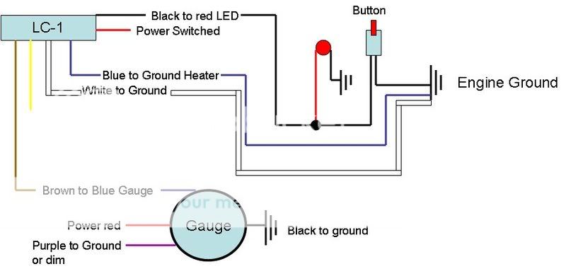
The LED will communicate the LC-1�s status. To monitor LC-1 status, connect the red wire
(Anode) of the included LED to the calibration wire (black) of the LC-1 and connect the black wire
(Cathode) of the LED to the ground wire of the momentary switch. The grounds to both the
cathode side of the LED and the Push button should be connected with the Heater ground.
a. Note: The included LED will fit the following hole size and panel thickness: a 5/32�
(0.155� - 0.158�) hole size and a panel thickness of 28�16gauge (0.031� - 0.062�).
b. Optionally, any 1.2V - 2.2V (1mA- 30mA) LED may be used. A typical LED has 2
wires called Anode and Cathode. The Cathode side is typically the shorter of the 2
wires or the black wire.
Pressing the push-button or connecting the black wire to ground (a three second press is
required with firmware version 1.10) starts a free air calibration process in the LC-1. MAKE SURE
THE SENSOR IS IN FREE AIR FOR THAT. See chapter 4 for details.
2 Mounting and Wiring the LC-1
1. Find a suitable location under your vehicle where the LC-1 body can be mounted. Using
zip ties or other suitable method, fasten the body of the LC-1 device securely to the framerails
or other mounting points as far away from the heat of the exhaust system as the sensor
cable allows. DO NOT zip-tie the LC-1 by the cables.
2. Route the cables from the LC-1 (except sensor cable) into the car interior under the dash.
3. LC-1 Cable connections:
A. Interface and power cables with 6 stripped ends*:
a. Red 12V supply
b. Blue Heater Ground
c. White System Ground
d. Yellow Analog out 1
e. Brown Analog out 2
f. Black Calibration wire
B. Serial In connection, 2.5mm stereo (female) marked as IN
C. Serial Out connection, 2.5 mm stereo (female) marked as OUT.
* 3.1 If you have an LC-1 with only 7 stripped ends the wiring is as follows:
a. Red 12V supply
b. Blue Heater Ground
c. White System Ground
d. Yellow Analog out 1
e. Brown Analog out 2
f. Green Analog Ground
g. Black Calibration wire
4. Connect the RED wire to a switched 12V source in your car. A switched 12V source
goes on as soon as the ignition on the car is on. Make sure the connection is fused with a
minimum fuse size of 5A.
5. The BLUE and WHITE wires should all be grounded to the same ground source.
Optimally, these (and any other MTS device ground) will be soldered to the same lug, and
connected to a single point. When this isn�t possible, connect each one to a separate lug,
and attach in close proximity. Multiple lugs on the same bolt is not optimal, and can result in
unwanted signal �noise.� When possible, soldering is always better than crimping. Please
see chapter 2.3 for more information on Electrical Grounding Concerns.
6. Optionally, the YELLOW (Analog out 1) and/or BROWN (Analog out 2) can be connected
to the analog inputs of other devices such as data loggers, ECUs, or gauges. If either one or
both of these wires are not being used isolate and tape the wire(s) out of the way. The default
analog outputs are as follows: Analog output one is 1.1V = 14 AFR and .1V = 15 AFR. This is
a simulated narrowband signal. Analog output two is setup as 0V = 7.35 AFR and 5V = 22.39
AFR. Note: The LC-1�s heater ground and system ground wires should share the same
grounding location of the analog input�s ground. Refer to chapter 2.2 for recommended
wiring schematics.
7. Optionally connect a momentary push-button switch between ground and the BLACK
calibration wire. Please refer to section 2.1.
Note: The use of the calibration wire is not necessary if the LC-1 is connected to Innovate
Motorsports� XD-16 digital gauge. If the wire is not are not being used, isolate and tape the
wire out of the way.
I DO NOT UNDERSTAND THIS PART AT ALL:
- 5 -
8. Optionally connect a indication LED (1.2-2.2V, 1-30mA is recommended) between the
calibration wire and ground. Please refer to section 2.1
2.1 Indicator LED and Calibration button hookup:
The LED will communicate the LC-1�s status. To monitor LC-1 status, connect the red wire
(Anode) of the included LED to the calibration wire (black) of the LC-1 and connect the black wire
(Cathode) of the LED to the ground wire of the momentary switch. The grounds to both the
cathode side of the LED and the Push button should be connected with the Heater ground.
a. Note: The included LED will fit the following hole size and panel thickness: a 5/32�
(0.155� - 0.158�) hole size and a panel thickness of 28�16gauge (0.031� - 0.062�).
b. Optionally, any 1.2V - 2.2V (1mA- 30mA) LED may be used. A typical LED has 2
wires called Anode and Cathode. The Cathode side is typically the shorter of the 2
wires or the black wire.
Pressing the push-button or connecting the black wire to ground (a three second press is
required with firmware version 1.10) starts a free air calibration process in the LC-1. MAKE SURE
THE SENSOR IS IN FREE AIR FOR THAT. See chapter 4 for details.
Last edited by mike25; Jul 21, 2008 at 09:46 PM.
Senior Member
Joined: 03-07-05
Posts: 1,733
Likes: 0
From: San Pedro/PV
its not that bad.
power to a power source. make sure its a clean source
ground to a lug. nothing else should be grounded to this same lug.
the led must also be grounded to the SAME PIECE OF METAL the power ground is connected to, but to a different lug.
brown wire = 0-5v analog output (connect to HPT box for logging, i think hole #4 if i remember correctly...ground the HPT box too)

Senior Member
Joined: 06-22-08
Posts: 1,320
Likes: 0
From: PA
ok im trying to figure out how to wire up this damn lc-1 to my car.. can someone make sense of this crap?:
2 Mounting and Wiring the LC-1
1. Find a suitable location under your vehicle where the LC-1 body can be mounted. Using
zip ties or other suitable method, fasten the body of the LC-1 device securely to the framerails
2 Mounting and Wiring the LC-1
1. Find a suitable location under your vehicle where the LC-1 body can be mounted. Using
zip ties or other suitable method, fasten the body of the LC-1 device securely to the framerails
2. Route the cables from the LC-1 (except sensor cable) into the car interior under the dash.
3. LC-1 Cable connections:
A. Interface and power cables with 6 stripped ends*:
a. Red 12V supply
b. Blue Heater Ground
c. White System Ground
d. Yellow Analog out 1
e. Brown Analog out 2
f. Black Calibration wire
B. Serial In connection, 2.5mm stereo (female) marked as IN
C. Serial Out connection, 2.5 mm stereo (female) marked as OUT.
* 3.1 If you have an LC-1 with only 7 stripped ends the wiring is as follows:
a. Red 12V supply
b. Blue Heater Ground
c. White System Ground
d. Yellow Analog out 1
e. Brown Analog out 2
f. Green Analog Ground
g. Black Calibration wire
7. Optionally connect a momentary push-button switch between ground and the BLACK
calibration wire. Please refer to section 2.1. Note: The use of the calibration wire is not necessary if the LC-1 is connected to Innovate
Motorsports� XD-16 digital gauge. If the wire is not are not being used, isolate and tape the
wire out of the way.
I DO NOT UNDERSTAND THIS PART AT ALL:
- 5 -
8. Optionally connect a indication LED (1.2-2.2V, 1-30mA is recommended) between the
calibration wire and ground. Please refer to section 2.1
2.1 Indicator LED and Calibration button hookup:
The LED will communicate the LC-1�s status. To monitor LC-1 status, connect the red wire
(Anode) of the included LED to the calibration wire (black) of the LC-1 and connect the black wire
(Cathode) of the LED to the ground wire of the momentary switch. The grounds to both the
cathode side of the LED and the Push button should be connected with the Heater ground.
a. Note: The included LED will fit the following hole size and panel thickness: a 5/32�
(0.155� - 0.158�) hole size and a panel thickness of 28�16gauge (0.031� - 0.062�).
b. Optionally, any 1.2V - 2.2V (1mA- 30mA) LED may be used. A typical LED has 2
wires called Anode and Cathode. The Cathode side is typically the shorter of the 2
wires or the black wire.
Pressing the push-button or connecting the black wire to ground (a three second press is
required with firmware version 1.10) starts a free air calibration process in the LC-1. MAKE SURE
THE SENSOR IS IN FREE AIR FOR THAT. See chapter 4 for details.
Oh and MAKE SURE THE BATTERY is off during the install. You only learn by doing, this should be a good project, it's pretty straight forward. Use solder for the extensions and terminals if at all possible.
its not that bad.
power to a power source. make sure its a clean source
ground to a lug. nothing else should be grounded to this same lug.
the led must also be grounded to the SAME PIECE OF METAL the power ground is connected to, but to a different lug.
brown wire = 0-5v analog output (connect to HPT box for logging, i think hole #4 if i remember correctly...ground the HPT box too)
power to a power source. make sure its a clean source
ground to a lug. nothing else should be grounded to this same lug.
the led must also be grounded to the SAME PIECE OF METAL the power ground is connected to, but to a different lug.
brown wire = 0-5v analog output (connect to HPT box for logging, i think hole #4 if i remember correctly...ground the HPT box too)
Last edited by theneelster; Jul 21, 2008 at 10:00 PM. Reason: Automerged Doublepost

Thread Starter
Senior Member
Joined: 03-07-06
Posts: 7,224
Likes: 1
From: west virginia
no its not hard at all...this is the part that gets me:
The LED will communicate the LC-1�s status. To monitor LC-1 status, connect the red wire
(Anode) of the included LED to the calibration wire (black) of the LC-1 and connect the black wire
(Cathode) of the LED to the ground wire of the momentary switch. The grounds to both the
cathode side of the LED and the Push button should be connected with the Heater ground.
a. Note: The included LED will fit the following hole size and panel thickness: a 5/32�
(0.155� - 0.158�) hole size and a panel thickness of 28�16gauge (0.031� - 0.062�).
b. Optionally, any 1.2V - 2.2V (1mA- 30mA) LED may be used. A typical LED has 2
wires called Anode and Cathode. The Cathode side is typically the shorter of the 2
wires or the black wire.
Pressing the push-button or connecting the black wire to ground (a three second press is
required with firmware version 1.10) starts a free air calibration process in the LC-1. MAKE SURE
THE SENSOR IS IN FREE AIR FOR THAT. See chapter 4 for details.
is it saying that both the ground(black wire) of the led and the push button need to be hooked up the heater wire, or is it saying that once you connect the push button/led together, that the second wire comming off the push button is the ground and that needs to be hooked to the heater wire?

Senior Member
Joined: 05-18-07
Posts: 975
Likes: 0
From: New Jersey
It was a piece of cake, think it through and you will be fine... Make sure you follow the directions on the gauge and connect it to LC-1's brown wire not the yellow wire as shown in the LC-1's instructions... The yellow wire caused my gauge to freak out when I first fired it up... Also make sure you carefully follow the calibration instructions read it, read it a second time, think it through and read it while you are doing it... I spent a total of about three hours installing mine this past weekend.
CA triple gauge A-pillar

Wideband calibration button and led

LC-1 installed under the hood

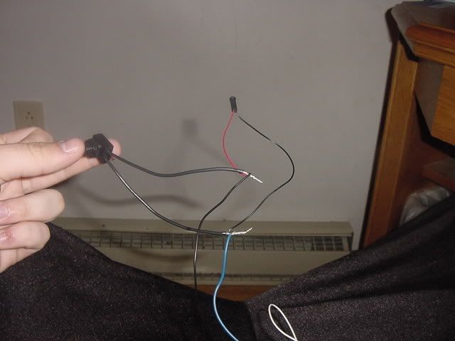
You need to parallel the LED with the switch between the LC-1's black wire and ground with the LED's red wire connected to the LC-1's black wire and the LED's black wire to ground...
CA triple gauge A-pillar
Wideband calibration button and led
LC-1 installed under the hood
no its not hard at all...this is the part that gets me:
The LED will communicate the LC-1’s status. To monitor LC-1 status, connect the red wire
(Anode) of the included LED to the calibration wire (black) of the LC-1 and connect the black wire
(Cathode) of the LED to the ground wire of the momentary switch. The grounds to both the
cathode side of the LED and the Push button should be connected with the Heater ground.
a. Note: The included LED will fit the following hole size and panel thickness: a 5/32”
(0.155” - 0.158”) hole size and a panel thickness of 28–16gauge (0.031” - 0.062”).
b. Optionally, any 1.2V - 2.2V (1mA- 30mA) LED may be used. A typical LED has 2
wires called Anode and Cathode. The Cathode side is typically the shorter of the 2
wires or the black wire.
Pressing the push-button or connecting the black wire to ground (a three second press is
required with firmware version 1.10) starts a free air calibration process in the LC-1. MAKE SURE
THE SENSOR IS IN FREE AIR FOR THAT. See chapter 4 for details.
is it saying that both the ground(black wire) of the led and the push button need to be hooked up the heater wire, or is it saying that once you connect the push button/led together, that the second wire comming off the push button is the ground and that needs to be hooked to the heater wire?
You need to parallel the LED with the switch between the LC-1's black wire and ground with the LED's red wire connected to the LC-1's black wire and the LED's black wire to ground...
Last edited by BRN169; Jul 21, 2008 at 10:27 PM. Reason: Automerged Doublepost
Thread Starter
Senior Member
Joined: 03-07-06
Posts: 7,224
Likes: 1
From: west virginia
It was a piece of cake, think it through and you will be fine... Make sure you follow the directions on the gauge and connect it to LC-1's brown wire not the yellow wire as shown in the LC-1's instructions... The yellow wire caused my gauge to freak out when I first fired it up... Also make sure you carefully follow the calibration instructions read it, read it a second time, think it through and read it while you are doing it... I spent a total of about three hours installing mine this past weekend.
CA triple gauge A-pillar
Wideband calibration button and led
LC-1 installed under the hood
You need to parallel the LED with the switch between the LC-1's black wire and ground with the LED's red wire connected to the LC-1's black wire and the LED's black wire to ground...
CA triple gauge A-pillar
Wideband calibration button and led
LC-1 installed under the hood
You need to parallel the LED with the switch between the LC-1's black wire and ground with the LED's red wire connected to the LC-1's black wire and the LED's black wire to ground...
lc-1 black wire>led red wire thenled blak wire>left side of push button and then right of push button>blue heater ground
Senior Member
Joined: 05-18-07
Posts: 975
Likes: 0
From: New Jersey
LC-1's white and blue, LED's black and one side of the switch to ground (same lug if possible)
The LC-1's black wire connects to both one leg of the switch and the red wire from the LED. The LED and the switch are not wired in series they need to be wired in parallel!!!
Thread Starter
Senior Member
Joined: 03-07-06
Posts: 7,224
Likes: 1
From: west virginia
no no no...
LC-1's white and blue, LED's black and one side of the switch to ground (same lug if possible)
The LC-1's black wire connects to both one leg of the switch and the red wire from the LED. The LED and the switch are not wired in series they need to be wired in parallel!!!
LC-1's white and blue, LED's black and one side of the switch to ground (same lug if possible)
The LC-1's black wire connects to both one leg of the switch and the red wire from the LED. The LED and the switch are not wired in series they need to be wired in parallel!!!
oh i will...i was the same way when i wired up my boost/oil gauges...
Last edited by mike25; Jul 21, 2008 at 10:48 PM. Reason: Automerged Doublepost

Senior Member
Joined: 11-11-05
Posts: 9,438
Likes: 0
From: Oceanside, Ca
Senior Member
Joined: 05-18-07
Posts: 975
Likes: 0
From: New Jersey
Thread Starter
Senior Member
Joined: 03-07-06
Posts: 7,224
Likes: 1
From: west virginia
im not too worried about that...ill just drill the hole to the exact size of the led and put a little bit of glue on from behind
Last edited by mike25; Jul 22, 2008 at 12:02 AM. Reason: Automerged Doublepost
Thread Starter
Senior Member
Joined: 03-07-06
Posts: 7,224
Likes: 1
From: west virginia
i was reading through the guide and it says that the yellow wire is a narrowband hookup and the brown is a 0-5v...question is if the gauge needs the brown wire then how the hell am i suppose to use it to hookup to hpt
Thread Starter
Senior Member
Joined: 03-07-06
Posts: 7,224
Likes: 1
From: west virginia
well i have the bung welded in. im trying to figure out this thing hooks up to hpt....i was told i need a 0-5v output...how can i do this when the gauge needs the 0-5v output as well?
Senior Member
Joined: 03-07-05
Posts: 1,733
Likes: 0
From: San Pedro/PV
youwould have to loop the connection through the HPT pro box. Basically, the HPT box would have to be permanently mounted in the vehicle somewhere. The HPT box will take the input, and it also has the capability to output simultaneously. Someone correct me if I'm wrong, I never attempted doing it that way.
My AEM shows on the gauge while simultaneously logging on hpt.
My AEM shows on the gauge while simultaneously logging on hpt.
Thread Starter
Senior Member
Joined: 03-07-06
Posts: 7,224
Likes: 1
From: west virginia
so basically id have to unhook the 0-5v from the gauge to hook it up to the box?...then again what if i was to splice the wire into two connectors...like add on a piece of the same gauge wire and then branch off of that

That is correct... The brown wire is 1-5v, the yellow with is only for a narrow band. I just installed my LC-1 with a DB-Red gauge last friday before Dan tuned me. Yea the one analog output is a bitch. When I met Dan and he pulled out his HPT box I was like yea you can use these black headphone jack looking plugs right..? Needless to say I spent the next few minutes pulling apart my A pillar and getting the brown wire off my gauge. Soo yea, if you want to have a wideband gauge and tune at the same time, you will need to split the wire or disconnect it temporarily...