
Appearance: How To: FXR Headlight Retrofits [Noob Guide with Pics]


How To: FXR Headlight Retrofits [Noob Guide with Pics]
Talked with two mods, said it was okay to post here till I am done with this how-to.. Need to edit several times and reserve several posts as there are a lot of pics.
Got my kit from TheRetrofitSource, Matt and Andrew answered a lot of my questions, they have really good customer service!
The Goods-
My setup is as followed:
Complete Retrofit Kit:
BI-XENON FX-R STAGE III KIT
Morimoto 3Five (35W) Long Cord Output Ballast
Morimoto 3Five 6000k D2S HID Bulbs (the containers say 5000k, but they're 6000k)
CCFL Angels: No
Re-Sealing Glue: Yes
Shrouds: E55-R
Concentric Rings
Relay: 9007
Package comes with a ballast tester.
Ordered a pair of headlight wire harnesses from a vendor here.
Ordered 194 Amber leds, and 3157 switchbacks
Pictures of the items for your reference...
FXR Projector:


Ballast:

HID Bulbs:


Re-Sealing Glue (Oci Butyl Rubber Glue... Comes with more than enough for the project)

Shrouds (E55-R):


Concentric Rings (they're the black rings):

Relay Harness (9007):

Ballast Tester:

Headlight Wire Harness:
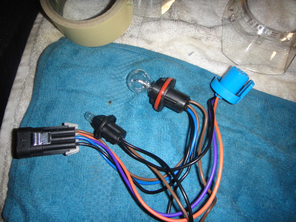
194 Led (replaces small bulb in the headlight wire harness):

3157 Switchbacks (replaces big bulb in the headlight wire harness):

Got my kit from TheRetrofitSource, Matt and Andrew answered a lot of my questions, they have really good customer service!
The Goods-
My setup is as followed:
Complete Retrofit Kit:
BI-XENON FX-R STAGE III KIT
Morimoto 3Five (35W) Long Cord Output Ballast
Morimoto 3Five 6000k D2S HID Bulbs (the containers say 5000k, but they're 6000k)
CCFL Angels: No
Re-Sealing Glue: Yes
Shrouds: E55-R
Concentric Rings
Relay: 9007
Package comes with a ballast tester.
Ordered a pair of headlight wire harnesses from a vendor here.
Ordered 194 Amber leds, and 3157 switchbacks
Pictures of the items for your reference...
FXR Projector:
Ballast:
HID Bulbs:
Re-Sealing Glue (Oci Butyl Rubber Glue... Comes with more than enough for the project)
Shrouds (E55-R):
Concentric Rings (they're the black rings):
Relay Harness (9007):
Ballast Tester:
Headlight Wire Harness:
194 Led (replaces small bulb in the headlight wire harness):
3157 Switchbacks (replaces big bulb in the headlight wire harness):
Last edited by intel; Jul 7, 2012 at 02:46 PM. Reason: Automerged Doublepost
Disassembly + Paint Prep (If you want to retain the chrome look, skip the second half of this post/section)
Cliffnotes on disassembly:
There are a couple threads on how to disassemble the headlights, so I'll make this brief.
1)Line oven with cardboard
2)Temperature setting I used was 235, left headlights in oven for 15 minutes.
3)Use gloves to take out headlights, pry apart lens. Be careful of tabs, used a flathead screwdriver to help separate lens from headlights.
4)Once the lens is off, there are 3 screws in the back of the headlights, I circled them in the picture below. They use a Torx-15. One screw may require a bit extender.

5)Once the screws are removed, the headlight housing will come out. (Ignore the colors, they were just test pieces)


6)All that is left is the reflector bowl. It's a ball and socket joint, so pull straight out so you don't break one of them like I did. I removed the screws from the painted reflector below prior to taking this picture, this is just for visualization/reference.

7)These are the reflector bowls.

(removed the middle piece on this picture, its a torx screw)

Paint Prep
To remove the chrome easily from the headlight housing and reflector bowl all you have to do is soak the stuff in outdoor strength bleach. Make sure you remove the screws on the reflector bowl prior to soaking in bleach so they don't rust. They use torx as well.

Here are some before and after pictures of the headlight housing:


Here are some before and after pictures of the reflector bowls:


To remove the chrome off the shrouds all I used was a 1:1 mixture of muriatic acid (I got it from Home Depot) and hydrogen peroxide (got it from a local drug store).

Soak the the shrouds in the mixture, you can actually see the mixture eat at the chrome.

Some before and after pictures of the shrouds:


And here's the painted product:
No clear coat:


With clear coat:


Used automotive paint for those that are wondering.
Cliffnotes on disassembly:
There are a couple threads on how to disassemble the headlights, so I'll make this brief.
1)Line oven with cardboard
2)Temperature setting I used was 235, left headlights in oven for 15 minutes.
3)Use gloves to take out headlights, pry apart lens. Be careful of tabs, used a flathead screwdriver to help separate lens from headlights.
4)Once the lens is off, there are 3 screws in the back of the headlights, I circled them in the picture below. They use a Torx-15. One screw may require a bit extender.
5)Once the screws are removed, the headlight housing will come out. (Ignore the colors, they were just test pieces)
6)All that is left is the reflector bowl. It's a ball and socket joint, so pull straight out so you don't break one of them like I did. I removed the screws from the painted reflector below prior to taking this picture, this is just for visualization/reference.
7)These are the reflector bowls.
(removed the middle piece on this picture, its a torx screw)
Paint Prep
To remove the chrome easily from the headlight housing and reflector bowl all you have to do is soak the stuff in outdoor strength bleach. Make sure you remove the screws on the reflector bowl prior to soaking in bleach so they don't rust. They use torx as well.
Here are some before and after pictures of the headlight housing:
Here are some before and after pictures of the reflector bowls:
To remove the chrome off the shrouds all I used was a 1:1 mixture of muriatic acid (I got it from Home Depot) and hydrogen peroxide (got it from a local drug store).
Soak the the shrouds in the mixture, you can actually see the mixture eat at the chrome.
Some before and after pictures of the shrouds:
And here's the painted product:
No clear coat:
With clear coat:
Used automotive paint for those that are wondering.
Last edited by intel; Jul 6, 2012 at 08:54 PM.
This section is how to setup a power source to test out the hids and ballast. I had a powersupply and thought it would be fun to use it for this project.
What's needed (starting from top left corner going clockwise):
4-Pin Molex Extension Cable
Powersupply
Ballast Tester (the kit only comes with one, I asked for an extra one from TRS and they happily sent an extra one with my order)
Wire Crimper

The 4pin molex extension cables (male) goes into the 4pin molex cable of the power supply (female)

Before we plug them in, you have to remove two of the wires from the 4pin molex extension. You want to keep the yellow wire (that's your 12v source) and the black wire next to it (that's your ground)


Plug the male end of the molex extension cables into the female end of the molex from the power supply.

Now get your ballast testers, and butt splice them to the molex extension cable. Yellow (12v source) splices to the orange wire of the ballast tester. Black from the molex extension goes to the black (ground) wire from the ballast tester.


Now the trick to power on the power supply is a paper clip. Contort the paper clip so it looks something like this.

From the power supply locate the 20 pin cable (it's the big connector).

Now insert the paperclip into the pin with green wire and then the pin with the black wire. You should see the fan spinning on the power supply. If it doesn't make sure the button on the back of the power supply is on the "I" position.

Power off the power supply, make sure the HID bulbs are connected to the ballast, connect ballast tester to ballast, power on and you should see light.

What's needed (starting from top left corner going clockwise):
4-Pin Molex Extension Cable
Powersupply
Ballast Tester (the kit only comes with one, I asked for an extra one from TRS and they happily sent an extra one with my order)
Wire Crimper
The 4pin molex extension cables (male) goes into the 4pin molex cable of the power supply (female)
Before we plug them in, you have to remove two of the wires from the 4pin molex extension. You want to keep the yellow wire (that's your 12v source) and the black wire next to it (that's your ground)
Plug the male end of the molex extension cables into the female end of the molex from the power supply.
Now get your ballast testers, and butt splice them to the molex extension cable. Yellow (12v source) splices to the orange wire of the ballast tester. Black from the molex extension goes to the black (ground) wire from the ballast tester.
Now the trick to power on the power supply is a paper clip. Contort the paper clip so it looks something like this.
From the power supply locate the 20 pin cable (it's the big connector).
Now insert the paperclip into the pin with green wire and then the pin with the black wire. You should see the fan spinning on the power supply. If it doesn't make sure the button on the back of the power supply is on the "I" position.
Power off the power supply, make sure the HID bulbs are connected to the ballast, connect ballast tester to ballast, power on and you should see light.
Last edited by intel; Jul 7, 2012 at 02:20 PM. Reason: Automerged Doublepost
Actual Retrofit Section
Take your reflector bowl and get a sharpie marker. Make a circle around the back of the bowl like this.


Now get your dremmel and start cutting. The cutting disc will only go so far.

Once you're done cutting around, break the flaps till it looks like this.

Now the dremmel cutting disc will be able to reach the middle piece, go ahead and cut that off.

You will see the circle marked from earlier, I used that as a reference point on how much I want to cut.


Use dremmel and smooth out circle.


Get your projector, reflector bowl, and 8-32 machine screws.

Put something on the tips of the screws so that it will mark the reflector bowls. Now get your power supply setup, power on the projectors and align the projectors till your line is straight. Once you are satisfied with the line put the screws through the projector to mark the spots. (Again ignore the color difference of the bowls)

Once you did that you should see the marked spots on the reflector bowls.

Drill those spots. I used a small bit then went progressively larger till the bolts were able to slide through the holes. Make sure you don't go to wide, you don't want the nuts to be able to go through those holes.


Cut off the excess thread of the bolts, make sure it fits in the headligt.


Make sure you feed those red wires, those are for the high beams.

I JB welded the back side of the reflector bowls. I felt more comfortable using this over silicone, if anyone wants to chime in their opinion feel free to do so. This was my first build so I am a novice. Jb Weld is a permanent solution.

At this point you can mount the reflector bowl back into the headlight. I made the mistake of not installing the shrouds first, you have more room for mounting the shrouds if you install them before putting the reflector bowl back inside the headlights. Install concentric rings onto shrouds, mount shrouds onto projector. (I used JB Weld to hold the shrouds onto the projectors, epoxy might be a better choice as its clear).

Install headlight housing, thread the three torx screws in.

Some people reuse the old glue, I didn't want to cheap out and regret this, so I bought some Oci-Butyl glue with my package. So I took a screwdriver and scooped out all the old glue when I took apart my lenses. You can also use a heat gun to reheat the glue and use a flathead screwdriver to help remove the glue. Line the headlight with the glue, put lens on, put in oven to soften the glue and press together the lens with the headlight for a couple of minutes.

Take your reflector bowl and get a sharpie marker. Make a circle around the back of the bowl like this.
Now get your dremmel and start cutting. The cutting disc will only go so far.
Once you're done cutting around, break the flaps till it looks like this.
Now the dremmel cutting disc will be able to reach the middle piece, go ahead and cut that off.
You will see the circle marked from earlier, I used that as a reference point on how much I want to cut.
Use dremmel and smooth out circle.
Get your projector, reflector bowl, and 8-32 machine screws.
Put something on the tips of the screws so that it will mark the reflector bowls. Now get your power supply setup, power on the projectors and align the projectors till your line is straight. Once you are satisfied with the line put the screws through the projector to mark the spots. (Again ignore the color difference of the bowls)
Once you did that you should see the marked spots on the reflector bowls.
Drill those spots. I used a small bit then went progressively larger till the bolts were able to slide through the holes. Make sure you don't go to wide, you don't want the nuts to be able to go through those holes.
Cut off the excess thread of the bolts, make sure it fits in the headligt.
Make sure you feed those red wires, those are for the high beams.
I JB welded the back side of the reflector bowls. I felt more comfortable using this over silicone, if anyone wants to chime in their opinion feel free to do so. This was my first build so I am a novice. Jb Weld is a permanent solution.
At this point you can mount the reflector bowl back into the headlight. I made the mistake of not installing the shrouds first, you have more room for mounting the shrouds if you install them before putting the reflector bowl back inside the headlights. Install concentric rings onto shrouds, mount shrouds onto projector. (I used JB Weld to hold the shrouds onto the projectors, epoxy might be a better choice as its clear).
Install headlight housing, thread the three torx screws in.
Some people reuse the old glue, I didn't want to cheap out and regret this, so I bought some Oci-Butyl glue with my package. So I took a screwdriver and scooped out all the old glue when I took apart my lenses. You can also use a heat gun to reheat the glue and use a flathead screwdriver to help remove the glue. Line the headlight with the glue, put lens on, put in oven to soften the glue and press together the lens with the headlight for a couple of minutes.
Last edited by intel; Sep 13, 2012 at 01:52 AM.
One thing I forgot to mention, before you seal reflector bowl and projectors, make sure the solenoid works. All you need is a 9 volt battery. Take one red tip and connect it to the positive terminal of the 9v battery and the other red tip and connect it to the negative terminal of the 9v battery. The red tips are not polarity sensitive so any tip will suffice. You should hear a click if it works.

Engine Bay install/wiring
The 9007 relay harness from TRS is already labeled for your convenience, but I'll just type the stuff out anyways.

-The black circles are your ground wires. I cut those terminals off and used a butt splice to extend the grounds wires to my strut bolts.
-The red circle is your power line, our batteries are in our trunks, so I cut that ring terminal off, butt spliced the wire to give me extra slack, and added a bigger ring terminal to get power from the the pole in the fuse box.
-The blue circle connects only to one of the head light harnesses, I used the driver side one. This may sound a bit confusing so I'll add some more pictures for clarification.
-Orange circles connects to the red wires of the projectors, I will show you how to set up the red wires.
-Yellow circles connect to the ballast.
-Gray circle connects to the Morimoto box below.

Used some locktite on the screws for the mounting brackets of the ballasts.

I took off my bumper so I could hide the ballast, this part is optional. I drilled two holes, sprayed the holes with some paint to prevent rust, used two bolts and nuts with nylon inserts.
Passenger side

Driver side

Ran the 9007 relay harness, connected the yellow connector of the 9007 harness to ballast.

Disconnect ground (-) from the battery before you proceed.
Ok now that the ballasts are securely mounted you can have a idea on how much extra wiring you will need for when you extend the ground and power cables.
I had a ground spot on my struts bolts, so I cut the original ground terminals off the 9007 relay, butt spliced the wires to extend it, crimped a new terminal. Make sure you use heatshrink wrap and/or waterproof butt splices. Use a heat gun to shrink. Don't ground all your stuff to one spot like I did lol, I was tired of donating blood to all the mosquitoes here so I connected to one spot to just save time from being outside any longer, I will fix this later.


Okay now for the power wire, again I cut the original terminal off, butt spliced it, used heat shrink wrap, extended the wire a bit, put a new ring terminal on, and connected it to the pole in the fuse box. Tighten down when done. It takes a 10mm socket.


Now that the ground and power cables are accounted for, I went back to my headlights and started setting up those red wires.
The projectors come with these items, find them.

Get the red pins and bend out the flap a little bit.

Push them in through the bottom of the connector, you'll know you have a secure connection if you cant pull those red pins out. Those flaps you bent out should "catch" inside the connector.

I bought some 90mm caps from TRS, Cut an "X" on the cap.

Feed the connector you just set up through the 90mm cap. Orange connector from the 9007 relay to your projectors (the red wires you just setup).

At this point you can also feed the metal braided cap from the ballast through the 90mm cap you can connect it to your HID bulbs.

Make sure you don't lose that yellow cap that goes inside the ballast cap.

Okay this part is important if you want your high beams to work.
The blue connector from the 9007 harness from TRS is pink/white/blue as seen below.

You need to swap the blue and white pins to make it look like this.

To pop out the pins you need a fine edge tip to bend the flaps back. (Sort of the opposite of what we did when we setup the red wires)

Okay, remember I said that blue cap from the 9007 harness will only be used on one side. I set it up on the driver side. In the pic below the left side is the blue cap from the 9007 relay, the right side is the blue connector from the headlight harness.

Both of these get connected (one from driver side, one from passenger side). The left connector is from the headlight harness, the right connector is from the car.

Finally, once everything was connected, just push the 90mm cap back into the headlight. It's sort of loose, any fix for this? Did anyone use the stock ones? I will see if I get any moisture in the headlight in the coming weeks when it rains.

Engine Bay install/wiring
The 9007 relay harness from TRS is already labeled for your convenience, but I'll just type the stuff out anyways.
-The black circles are your ground wires. I cut those terminals off and used a butt splice to extend the grounds wires to my strut bolts.
-The red circle is your power line, our batteries are in our trunks, so I cut that ring terminal off, butt spliced the wire to give me extra slack, and added a bigger ring terminal to get power from the the pole in the fuse box.
-The blue circle connects only to one of the head light harnesses, I used the driver side one. This may sound a bit confusing so I'll add some more pictures for clarification.
-Orange circles connects to the red wires of the projectors, I will show you how to set up the red wires.
-Yellow circles connect to the ballast.
-Gray circle connects to the Morimoto box below.
Used some locktite on the screws for the mounting brackets of the ballasts.
I took off my bumper so I could hide the ballast, this part is optional. I drilled two holes, sprayed the holes with some paint to prevent rust, used two bolts and nuts with nylon inserts.
Passenger side
Driver side
Ran the 9007 relay harness, connected the yellow connector of the 9007 harness to ballast.
Disconnect ground (-) from the battery before you proceed.
Ok now that the ballasts are securely mounted you can have a idea on how much extra wiring you will need for when you extend the ground and power cables.
I had a ground spot on my struts bolts, so I cut the original ground terminals off the 9007 relay, butt spliced the wires to extend it, crimped a new terminal. Make sure you use heatshrink wrap and/or waterproof butt splices. Use a heat gun to shrink. Don't ground all your stuff to one spot like I did lol, I was tired of donating blood to all the mosquitoes here so I connected to one spot to just save time from being outside any longer, I will fix this later.
Okay now for the power wire, again I cut the original terminal off, butt spliced it, used heat shrink wrap, extended the wire a bit, put a new ring terminal on, and connected it to the pole in the fuse box. Tighten down when done. It takes a 10mm socket.
Now that the ground and power cables are accounted for, I went back to my headlights and started setting up those red wires.
The projectors come with these items, find them.
Get the red pins and bend out the flap a little bit.
Push them in through the bottom of the connector, you'll know you have a secure connection if you cant pull those red pins out. Those flaps you bent out should "catch" inside the connector.
I bought some 90mm caps from TRS, Cut an "X" on the cap.
Feed the connector you just set up through the 90mm cap. Orange connector from the 9007 relay to your projectors (the red wires you just setup).
At this point you can also feed the metal braided cap from the ballast through the 90mm cap you can connect it to your HID bulbs.
Make sure you don't lose that yellow cap that goes inside the ballast cap.
Okay this part is important if you want your high beams to work.
The blue connector from the 9007 harness from TRS is pink/white/blue as seen below.
You need to swap the blue and white pins to make it look like this.
To pop out the pins you need a fine edge tip to bend the flaps back. (Sort of the opposite of what we did when we setup the red wires)
Okay, remember I said that blue cap from the 9007 harness will only be used on one side. I set it up on the driver side. In the pic below the left side is the blue cap from the 9007 relay, the right side is the blue connector from the headlight harness.
Both of these get connected (one from driver side, one from passenger side). The left connector is from the headlight harness, the right connector is from the car.
Finally, once everything was connected, just push the 90mm cap back into the headlight. It's sort of loose, any fix for this? Did anyone use the stock ones? I will see if I get any moisture in the headlight in the coming weeks when it rains.
Last edited by intel; Jul 6, 2012 at 09:50 PM. Reason: Automerged Doublepost
Cutoff lines, pics on the car. More pictures to come.
This was an initial test in my friend's living room lol. I used the power supply to power them up. The surface wasn't really level, it was on an ironing board.

Picture of the car:

Picture of the cutoff line:
Not really too great of a pic, I will try to get better pictures later.

This was an initial test in my friend's living room lol. I used the power supply to power them up. The surface wasn't really level, it was on an ironing board.
Picture of the car:
Picture of the cutoff line:
Not really too great of a pic, I will try to get better pictures later.
Last edited by intel; Jul 6, 2012 at 08:48 PM.
Updates
This was my first How-To post and first retrofit project. It was a fun learning experience, I provided all these pictures to help anyone out that will want to attempt this. So learn from my mistakes :]
For 05-06 cobalts don't buy vled switchbacks! The Daytime Running Lights (DRLs) run through the turn signal, this is a no no.. I learned the hardway...
Been about two weeks and can happily report that there have been no problems with condensation/leaks in these headlights~
My first mistake was that I didn't align the the projectors first in the reflector bowl. I just put the projector in the reflector bowl and marked the spots that I wanted to drill. The drill spots were pretty much level so I wasn't really to worried about this (what I mean by level is that the two top spots and two bottom spots were "straight." So again, the proper way to do this is power the HIDs make sure your cutoff line is pretty straight, use a dab of epoxy as suggested below to keep the projectors in place THEN mark the holes you want to drill in the reflector bowl.
My second mistake was that I should of probably made the holes a little bit bigger in the reflector bowl so that the projector would fit a bit deeper into the reflector bowl. With the measurements I used, the back of the projector doesn't really stick out of the back of the headlights as much as I would of liked it to. Here are some pictures of what I mean. My hole in the reflector bowl was a little bit under 3". So I would try making the hole wider, and seeing if the back of the projector clears the back of the headlights better. Test this out before you seal the reflector bowls. This is what I messed up on.
Last edited by intel; Jul 25, 2012 at 11:29 PM.

^agreed. But I love watching a good project and im a monster fan of e55 shrouds, and FXR's are the best aftermarket projector you can get! only ones better are a few OEMs like TL, LS460 but they are gargantuan in size.
I was too ***** to attempt an fxr retro mainly because i dont have the time and wasnt confident. But after all you just bought way to cheap out on the 9007 Harness, order a real on from TRS, its 3x the size.
I was too ***** to attempt an fxr retro mainly because i dont have the time and wasnt confident. But after all you just bought way to cheap out on the 9007 Harness, order a real on from TRS, its 3x the size.

Did you read the first line of the first post
I did get the 9007 harness from TRS, I bought the complete kit from them.
Last edited by intel; Jul 6, 2012 at 05:00 PM.

New Member
Joined: 03-31-11
Posts: 138
Likes: 0
From: Skamokawa, WA
So, does that screw near the back of the solenoid slide into that notch at the bottom of the reflector where the bi-xenon wire will be going through? I didn't see any pictures of you test firing them and checking the alignment. So I assume you were able to use that notch to get it perfect the first time.
So, does that screw near the back of the solenoid slide into that notch at the bottom of the reflector where the bi-xenon wire will be going through? I didn't see any pictures of you test firing them and checking the alignment. So I assume you were able to use that notch to get it perfect the first time.


So, does that screw near the back of the solenoid slide into that notch at the bottom of the reflector where the bi-xenon wire will be going through? I didn't see any pictures of you test firing them and checking the alignment. So I assume you were able to use that notch to get it perfect the first time.
New Member
Joined: 03-31-11
Posts: 138
Likes: 0
From: Skamokawa, WA

See where the bottom screw is? That! Is that part sittin' inside that notch where that little hole is where you feed the bi-xenon wire through and where the little "bulb cap" used to go through? If so, that's an awesome way of getting the alignment perfect the first time. I won't be upgrading from MH1s to FX-Rs 'til next year. Meanwhile, I do request you make lots of driving videos showing Low and High beams and post them on YouTube. Someone else on HID Planet did an FX-R 3.0 retrofit to their Cobalt, but it was kinda sloppy.
@kcg795
Ohhhhhh, I know what you're talking about now lol. ya I was thinking the same thing when I went to mount the projectors to the reflector bowl. Unfortunately it's off by a little bit, I wasn't able to "rest" that part on the notch. I was thinking of maybe sanding it down with a dremmel, but decided not to go that route.
@Slowbalt2000
That's what the place recommended when I got my alignment.
@breds2k
Ya, I probably should of aligned first then drilled holes lol. The lines aren't to bad though.
Last edited by intel; Jul 7, 2012 at 02:23 AM.
New Member
Joined: 03-31-11
Posts: 138
Likes: 0
From: Skamokawa, WA
I'm just gonna use a 2 3/4" hole saw on mine. That way, I get a perfect round hole. I'm still brainstorming on how I want to seal the back of my headlights when I reretrofit them. I have Mini H1s now and I'm using the original rubber thing. I do get a little moisture in the Winter still. I might try the rubber cap like you did, but reroute the high voltage line through a hole I can drill in the back somewhere and sealed with silicone. That line would be an AMP to D2S adapter wire anyway since I plan to reuse my 3Five ballast that have the AMP connections. I've also seen some people drill a hole below the opening and feed the bi-xenon wire through that. I figure rerouting the wires through dedicated holes and sealing those holes would make it easier to seal the main hole up and reduce the chances of moisture. Eh, I got 'til next year to get this all figured out.
I still would like to see some video of your new lights in action. Also, how's the foreground limiter?
I still would like to see some video of your new lights in action. Also, how's the foreground limiter?
@kcg795
Ya, I will definitely try to get some videos up when I get some time. I've just been really busy lately. If I can find a 1080p recorder that would be optimal, I think my camera that I took the pictures with can record in 720p, so that might have to do. The difference between 720p and 1080p is minimal at best if I encode at a high bitrate anyways...
Ya let me know how the silicone turns out. I was just really familiar with JB putty weld, that stuff is amazing. I think I was able to seal the reflector bowl pretty well with that stuff. I just didn't know how hot the projectors would get and if the silicone would hold up to it.
Also with the foreground limiter, I believe they got rid of that with the FXR 3.0, I just use my fog lights when needed now.

