
4x4 Rock Buggy TC 2.4 Build


Thread Starter
Junior Member
Joined: 03-03-14
Posts: 415
Likes: 0
From: Florida
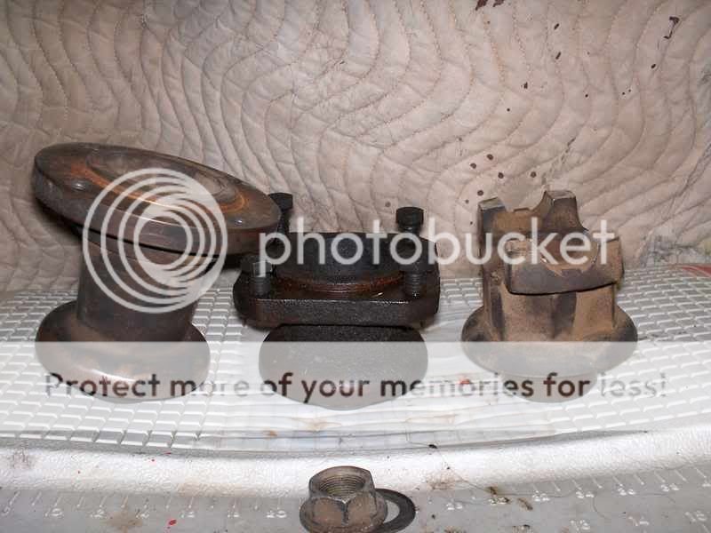
While I wait on the steering pump bracket to come back from the laser cutter and for inspiration to hit on the driveshafts I decided to start working on my axles. It was a slow day in the shop. The bandsaw blade broke, the lathe broke, some diesel pumps broke that I used to fill the shop heater with. After that was all fixed I barely had enough time left to make these carrier alignment pucks in the lathe:

They mount where the Ford 9" carrier bearings would normally go. The third member is installed into the housing and then an alignment bar is inserted as shown. More alignment pucks go in the knuckles to keep everything straight while they are welded onto the housing. The bar is just slid in temporarily in this pic for reference.

That is not the actual third member that will be used in the axles. It is an OEM junker that is now dedicated to aligning custom axles for the rest of its life. My housings are custom aftermarket as well as both third members. The rear axle has an ARB air locker, the front has a Detroit. 5.43 gears in both. I haven't posted pics of them yet but they have been laying on the floor in my shop this entire time. Front and rear steering knuckles come off of a 2006 F-350 Dana 60 front axle.
As I finished this up the laser cutter called and said that my order was ready. They're about 45 minutes away and I was about ready to start throwing tools around the shop so I decided to put everything up and go get my parts before I broke some more ****. It was too dark to get good pics of the bracket by the time I got it. I'll post some later when I have time to install it though.
They mount where the Ford 9" carrier bearings would normally go. The third member is installed into the housing and then an alignment bar is inserted as shown. More alignment pucks go in the knuckles to keep everything straight while they are welded onto the housing. The bar is just slid in temporarily in this pic for reference.
That is not the actual third member that will be used in the axles. It is an OEM junker that is now dedicated to aligning custom axles for the rest of its life. My housings are custom aftermarket as well as both third members. The rear axle has an ARB air locker, the front has a Detroit. 5.43 gears in both. I haven't posted pics of them yet but they have been laying on the floor in my shop this entire time. Front and rear steering knuckles come off of a 2006 F-350 Dana 60 front axle.
As I finished this up the laser cutter called and said that my order was ready. They're about 45 minutes away and I was about ready to start throwing tools around the shop so I decided to put everything up and go get my parts before I broke some more ****. It was too dark to get good pics of the bracket by the time I got it. I'll post some later when I have time to install it though.
 Moderator
Thread Starter
Junior Member
Joined: 03-03-14
Posts: 415
Likes: 0
From: Florida
I'm trying to model as much of the axles in Solidworks as possible before I cut my custom housings. I've only had a couple hours here and there at the shop to get anything done so far this week. I won't be able to get in a full day at any point so I'm just spending the little bits of time measuring and modeling. I'm making my axle housings use existing axle shafts for a few reasons. So modeling it all up should give me reassurance before I cut a $1000 housing.
This is the yoke portion of the inner dana 60 front axle shaft. I can add however much shaft to it that I want. It's not an exact replica but the dimensions that matter to me in terms of mocking up the axle are all there and accurate.

When I build my housings in SW I will make everything dependant on shaft length so that simply changing that propagates the appropriate changes to the housing itself. This will allow me to experiment with the various OEM shaft lengths to obtain optimal pinion offsets for my drive train.
I also drew up a Spicer 1480 universal joint because it's fun and will allow me to mate the outer stub shaft to the inner in the drawings:

I've also modeled my inner knuckle with adapter sleeve that will weld onto the ends of the tubes. I forgot to save an image of that and I'm no longer on my computer with SW to do it. I'll get that up later.
This is the yoke portion of the inner dana 60 front axle shaft. I can add however much shaft to it that I want. It's not an exact replica but the dimensions that matter to me in terms of mocking up the axle are all there and accurate.
When I build my housings in SW I will make everything dependant on shaft length so that simply changing that propagates the appropriate changes to the housing itself. This will allow me to experiment with the various OEM shaft lengths to obtain optimal pinion offsets for my drive train.
I also drew up a Spicer 1480 universal joint because it's fun and will allow me to mate the outer stub shaft to the inner in the drawings:
I've also modeled my inner knuckle with adapter sleeve that will weld onto the ends of the tubes. I forgot to save an image of that and I'm no longer on my computer with SW to do it. I'll get that up later.


Thread Starter
Junior Member
Joined: 03-03-14
Posts: 415
Likes: 0
From: Florida
I own an old-school manual lathe and an old 5x10 CNC Plasma table that I do prototypes on. I also own a company that sells laser-cut parts to the offroad industry. (Patooyee's Parts - Designer and manufacturer of hardcore rockwell and other offroad parts.) I outsource the laser cutting as well as my bigger machine work jobs. Small lathe jobs that won't take me long and are within my low-level skill set I do on my own. I outsource enough laser cutting to where I can normally mix my personal parts in with my company orders since the quality is so much higher than with my plasma table. When I can't coordinate stuff like that in a timely manner I fall back to my plasma table.


This is for the power steering pump? Perhaps I missed the question earlier, but why not fab a bracket to have it fit in the A/C compressor location since that's not going to be there? Also, are you not running the alternator?
Thread Starter
Junior Member
Joined: 03-03-14
Posts: 415
Likes: 0
From: Florida
Yes, that is is the ps pump. It needed its own belt track because the pump needs to spin at roughly half engine rpm. So I used the RWD crank pulley to get the second smaller front pulley which drives the bigger PS pulley at about half engine rpm. So when my engine is at 7000rpm the pump will only be around 3700.
I actually did experiment with a booty-fabbed bracket down by where the compressor was but the way that spacing worked out was just better on the front of engine like this. I will fab a reservoir that mounts directly to the pump to make fluid intake as efficient as possible this way, too.
The alternator is still there, just out of view to the right in the bottom pick and in the top right corner of the first pic.


Thread Starter
Junior Member
Joined: 03-03-14
Posts: 415
Likes: 0
From: Florida
Thread Starter
Junior Member
Joined: 03-03-14
Posts: 415
Likes: 0
From: Florida
Seems like everything at the shop and life has been fighting me recently but I finally had a mildly-productive day yesterday. Got most of my transmission output shafts done. This is the rear one. That is a cut-down CV shaft welded to a cut-down NP241 transfer case front output shaft with the 1350 CV flange welded to that.

I'm doing basically the same for the front but didn't quite finish it last night and didn't get pics of it. A shortened 1350 CV front driveshaft sourced from an F-350 will bolt to that flange and then to my axles.
Also built the bracket to tie the nose cone of the trans to the side of the block. Made it out of aluminum just because I can and because it doesn't seem right to not match the beautiful aluminum block. I wanted to make the PS pump bracket above aluminum as well but was afraid the tensioner bolt would gall it.

I also re-appropriated this steering reservoir from an old build of mine. The company that made these kind of fucked up the design. It had a small wall blocking the fluid outlet which tended to cause the pump to starve for fluid. They followed that up with a threaded fitting which further reduced the diameter that fluid could move through. Lastly, they epoxied it all together which ultimately was the cause of its demise as it exploded from internal pressure buildup. So I took it all apart, burnt the epoxy off, cleaned it all up, welded it back together, drilled the blocking wall out, and welded a fitting over the threaded port so as not to reduce port diameter any more. That is a -16 fitting on it now which matches the port on the pump:

And now life is going to interrupt again. I work the rest of this week then go to Disney World with my wife and daughter for a week and then work the entire week after I get back. So it will be March before I see the shop again. :-|
I'm doing basically the same for the front but didn't quite finish it last night and didn't get pics of it. A shortened 1350 CV front driveshaft sourced from an F-350 will bolt to that flange and then to my axles.
Also built the bracket to tie the nose cone of the trans to the side of the block. Made it out of aluminum just because I can and because it doesn't seem right to not match the beautiful aluminum block. I wanted to make the PS pump bracket above aluminum as well but was afraid the tensioner bolt would gall it.
I also re-appropriated this steering reservoir from an old build of mine. The company that made these kind of fucked up the design. It had a small wall blocking the fluid outlet which tended to cause the pump to starve for fluid. They followed that up with a threaded fitting which further reduced the diameter that fluid could move through. Lastly, they epoxied it all together which ultimately was the cause of its demise as it exploded from internal pressure buildup. So I took it all apart, burnt the epoxy off, cleaned it all up, welded it back together, drilled the blocking wall out, and welded a fitting over the threaded port so as not to reduce port diameter any more. That is a -16 fitting on it now which matches the port on the pump:
And now life is going to interrupt again. I work the rest of this week then go to Disney World with my wife and daughter for a week and then work the entire week after I get back. So it will be March before I see the shop again. :-|
Thread Starter
Junior Member
Joined: 03-03-14
Posts: 415
Likes: 0
From: Florida
First I cut the bell of the CV shaft with a cutting wheel on a grinder. That left enough meat to where I could chuck the shaft up in the lathe and I turned what was left of the back of the bell down to 2.25" and trued up the face.
Then I cut the NP241 front output shaft with a cutting wheel, chucked it up on the lathe, and machined a 2.249" bore in that for the machined CV shaft to press into.
The section that was left of that shaft was bigger than the splined portion of the yoke so I chucked the yoke up in the lathe and bored that out to the right diameter to press onto it all.
I pressed it all together and welded.
I'm sure its not perfect, my lathe isn't perfect. But it's good enough for a 4x4 buggy that will never go faster than 50mph with unbalanced 40" comp-compound tires mounted on non-DOT beadlock wheels.
Thread Starter
Junior Member
Joined: 03-03-14
Posts: 415
Likes: 0
From: Florida
Here's a generic pic of a CV shaft from the net:

I only used the back section of the green portion.
Then here is the NP241 output shaft:

I only used the lower right corner portion, about 1/16" into the beginning of the splines.
Then here is the yoke I used:
(Generic internet pic but mine is like the one in the middle.)
I spent the vast majority of my day yesterday standing in front of the lathe. I still have some more lathe work to do for the front shaft, but I'm 2/3 done with it.
I just need to prove that these yokes will work. If they do and they eventually break I will have them custom made out of a single piece of heat treated chromoly.
I only used the back section of the green portion.
Then here is the NP241 output shaft:
I only used the lower right corner portion, about 1/16" into the beginning of the splines.
Then here is the yoke I used:
(Generic internet pic but mine is like the one in the middle.)
I spent the vast majority of my day yesterday standing in front of the lathe. I still have some more lathe work to do for the front shaft, but I'm 2/3 done with it.
I just need to prove that these yokes will work. If they do and they eventually break I will have them custom made out of a single piece of heat treated chromoly.
Thread Starter
Junior Member
Joined: 03-03-14
Posts: 415
Likes: 0
From: Florida
What are the flow rates of the pumps ya'll are using on boosted engines? I'm calculating that I should require less than 190lph. That just seems so small coming from my background of V8's and it's weirding me out.
I don't think that many of the SS guys change out their fuel pumps.
Grain of salt here, comment taken from a thread talking about stock LSJ fuel pump flow:
L61 OEM replacement pump flows 181lph
http://www.oreillyauto.com/site/c/de...3002/02535.oap
Grain of salt here, comment taken from a thread talking about stock LSJ fuel pump flow:
http://www.oreillyauto.com/site/c/de...3002/02535.oap