coolant flow
 03-31-2010, 02:57 PM
#1
Senior Member
Thread Starter

coolant flow
i know my drawing is gay or what not but bear with it..
with option b and second heat exchanger, is this how the flow of plumming goes?

with option b and second heat exchanger, is this how the flow of plumming goes?


 04-01-2010, 12:02 AM
#9
Senior Member

All you have to do is make sure the laminovas are the right way and change the plumbing so instead of going to the middle nipple it goes in to the other two. I have seen people do the plumbing either way. I don't know how much of a difference it makes though.
04-01-2010, 02:31 AM
#10
Senior Member
iTrader: (1)

Join Date: 02-03-09
Location: Phoenix, Arizona
Posts: 4,881
Likes: 0
Received 0 Likes
on
0 Posts
You said two lines going to the ic. I was assuming you meant the heat exchanger, not the Intake manifold endplate. Two in and one out is how you are supposed to run the dual pass.
04-01-2010, 08:12 PM
#11
Senior Member
Thread Starter
more questions!
this is the picture of the intercooler pump, just so i dont **** it up, (its always better to be safe!) the upper hose is IN and the hose going left is OUT yes??~

this is the picture of the intercooler pump, just so i dont **** it up, (its always better to be safe!) the upper hose is IN and the hose going left is OUT yes??~
04-01-2010, 09:12 PM
#12
Senior Member


this is a stock system with the option B tank and the T bottle reservoir eliminated. step 1.
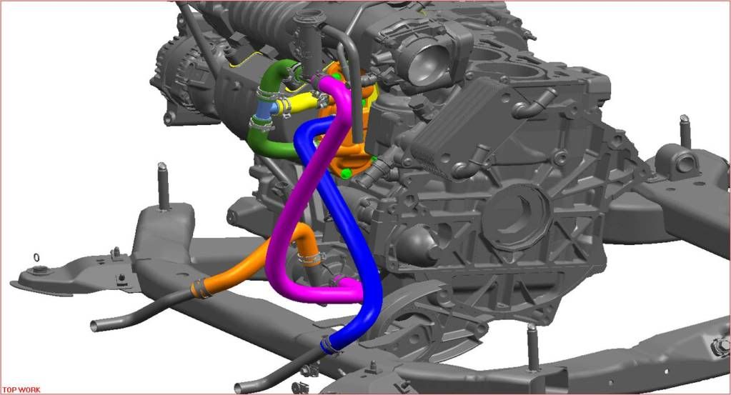
this is the dual pass with the stock reservoir.
Pump out is the orange hose. pump in is the pink hose. if you want to add an HE its simple: out of the stock h/e goes to the in of the new FM h/e. Out of the FM h/e goes to the middle port of the dual pass end plate... hope this helps
put another way: the two dual pass upper and lower ports need to come out and go to a plastic T, (A "Y" is better) then one line up to another "T" where one leg of the T goes to the coolant reservoir (Option B) and the other leg goes down to the center port of the intercooler pump (its "up" in your photo) Then off you go to the H/E that you have.
Note. You hoses should be nicely curved (moulded bends are best) when turning corners, NO kinks, and you need to re configure the Laminova tubes....
The cores should be OooO. simple. be careful removing them ifyou squeeze the ends it is over. very hard to do right
also:
There are 4 slots cut through the laminova fins. The two wider slots should be clocked toward the inlet and outlet ports of the IM.
Thanks to Eric Bristol for pointing out the slot positioning. They may be wrong from the get go....
Last edited by qwikredline; 04-01-2010 at 09:12 PM. Reason: Automerged Doublepost

Thread
Thread Starter
Forum
Replies
Last Post