Cam and crank shaft signal help.
 09-12-2014, 02:54 PM
#1
New Member
Thread Starter

Join Date: 05-15-13
Location: Edmonton
Posts: 37
Likes: 0
Received 0 Likes
on
0 Posts
Cam and crank shaft signal help.
Hi guys,
I have some basic questions about this engines cam and crank signals and I can't seem to find reliable answers anywhere.
The shop manual has this to say about the camshaft pulses.
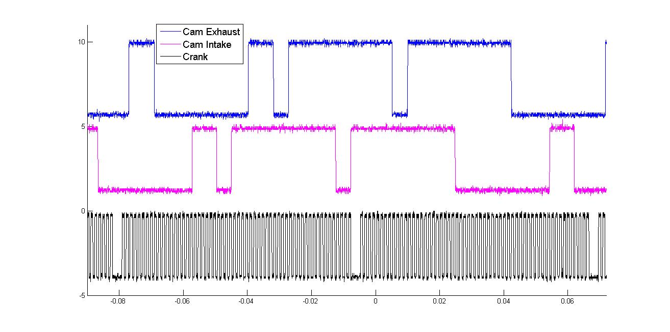
Below is a picture of the cam and crank signals from that I took from my engine. However, from this picture you can see that there aren't 4 different pulse sizes in the CMP signal, there are only 2 different sizes. Also the camshaft pulses are unaligned. What does that mean?
If anyone could help me out with this it would be greatly appreciated. I'm in the process of having a new engine controller run the fuel and injection timing of my engine, and I need to know the answers. I would prefer to avoid the brute force method of taking the spark plugs out and looking at it manually. It would be a pretty big pain trying to find where on the cam and crankshaft signals the engine is at with that method.
Thanks.
I have some basic questions about this engines cam and crank signals and I can't seem to find reliable answers anywhere.
- Where is TDC of cylinder one on the crank or cam signal? Is it on either the rising or fall edge of the first signal after the gap? What do the different camshaft pulses mean?
- Is the firing order 1-3-4-2? Does that mean if cylinder 1 is at TDC of the compression stroke at 0 degrees, that the offsets for cylinder 2, 3, and 4 respectively are 540, 180, and 360 degrees?
- Also just to be safe, what side of the engine is cylinder 1 and what side for cylinder 4? Which is on the bell housing side and which is on the pulleys side?
The shop manual has this to say about the camshaft pulses.
Both of the CMP sensors provide four signal pulses every camshaft revolution. Each notch, or feature of the reluctor wheel is of a different size which is used to identify the compression stroke of each cylinder and to enable sequential fuel injection.
If anyone could help me out with this it would be greatly appreciated. I'm in the process of having a new engine controller run the fuel and injection timing of my engine, and I need to know the answers. I would prefer to avoid the brute force method of taking the spark plugs out and looking at it manually. It would be a pretty big pain trying to find where on the cam and crankshaft signals the engine is at with that method.
Thanks.
 09-30-2014, 04:27 PM
#3
New Member
Thread Starter
Join Date: 05-15-13
Location: Edmonton
Posts: 37
Likes: 0
Received 0 Likes
on
0 Posts
I'm quite shocked that no tuners here know this information. Has no one tried running a different controller other than the stock one? Is this information embedded in HPtuners anywhere? I have been looking but haven't found anything.
10-03-2014, 06:42 PM
#4
New Member

Truth is i have no idea how to answer your questions but i think i can figure it out from the picture; lol.
Exhaust cam leads intake by about 180 crank degrees. you also know that exhaust closes somewhere around TDC of cylinder 1.
Generally isn't the missing tooth in the crank sensor wheel TDC???
also, look at the pictures on google of the LNF cams, and you can see the 4 teeth that generate your image are not in the same position on both intake and exhaust, i'm guessing that's why your cam signals aren't 180% out of phase, because the cam teeth are phased differently.
Easiest way to figure this out would be to take a few parts off the engine and figure it out by physical measurements; or find a good gm dealership technician that might be willing to share some knowledge.
Nobody answered to you because i don't think most tuners have access to oscilloscopes. Plus this forum is not very technical, maybe u'd have better luck on the HP tuner forum.
what are you trying to do with all this? it doesn't fall within the real of "tuning".
10-07-2014, 12:22 PM
#5
New Member
Thread Starter
Join Date: 05-15-13
Location: Edmonton
Posts: 37
Likes: 0
Received 0 Likes
on
0 Posts
Essentially what I'm trying to do is implement my own engine controller. The reason for this is I need to be able to change injection timing and pulse width on the fly. Having to key off and then back on the engine can't cut it for the type of research I'm doing. Thus I'm trying to implement my own controller that can change injection timing on the fly. I need to know these signals so I can first have my controller understand what is going on in the engine so it can know properly when to inject and what not.

Thread
Thread Starter
Forum
Replies
Last Post