
Keep going to limp mode


Thread Starter
New Member
Joined: 12-10-12
Posts: 29
Likes: 0
From: Houston / Katy, TX
Keep going to limp mode
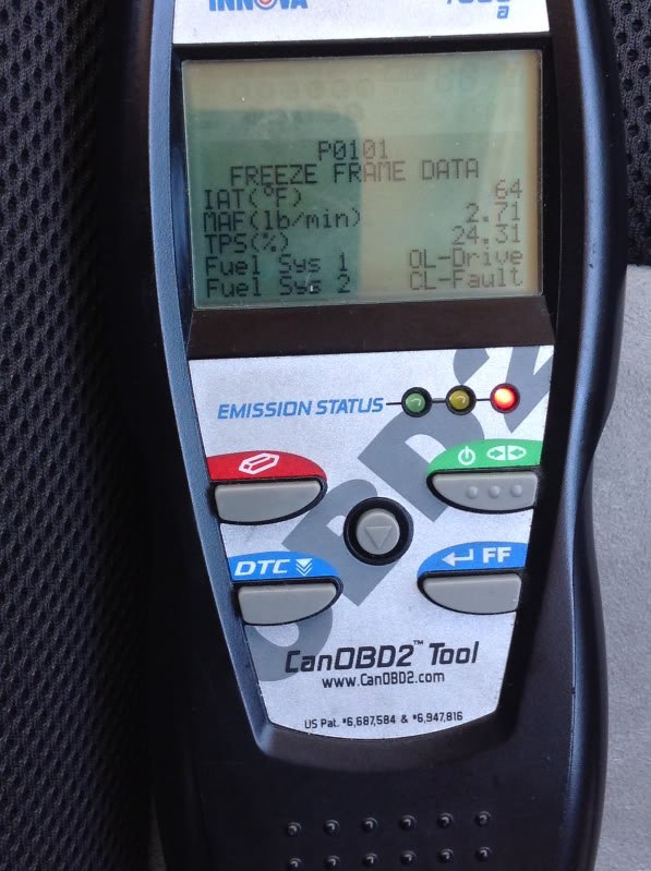
Everytime I do a full throttle run or push up too 10 psi or more of boost I go into limp mode and get code p0101 MAF performance or range. Does any one know what cold be going on? And I've replaced the MAF already. I could use some input right bout now.
Thread Starter
New Member
Joined: 12-10-12
Posts: 29
Likes: 0
From: Houston / Katy, TX
Yea I checked the wires and found one loose but I fixed it already but still having this issue and it a new MAF sensor too
Thread Starter
New Member
Joined: 12-10-12
Posts: 29
Likes: 0
From: Houston / Katy, TX

You can manage some of this stuff at home.
Originally Posted by GM Service Book
Conditions for Setting the DTC
The ECM detects that the measured MAF is not within range of the calculated airflow based on throttle angle and engine speed.
AND
� The ECM detects a significant error in the long term fuel trim at cruising speed.
OR
� The ECM detects that the measured MAF is not within range of the calculated model that is derived from MAP.
Originally Posted by GM Service Book
Circuit/System Verification
Verify that restrictions do not exist in the exhaust system. Refer to Restricted Exhaust.
Verify that an exhaust leak does not exist, including the mating surface area between the turbocharger and the exhaust manifold.
Ignition OFF for 90 seconds, determine the current vehicle testing altitude.
Ignition ON, engine OFF, observe the scan tool BARO parameter, Boost Pressure Sensor parameter, and MAP Sensor parameter. Compare the parameters to the Altitude Versus Barometric Pressure table. The parameters should be within the specified range indicated in the table.
Engine operating at idle, observe the scan tool MAF Sensor parameter. The reading should be between 1,700-3,200 Hz.
A wide open throttle (WOT) acceleration from a stop should cause the MAF sensor parameter on the scan tool to increase rapidly. This increase should be from 2-6 g/s at idle to greater than 200 g/s at the time of the 1-2 shift.
Operate the vehicle within the Conditions for Running the DTC to verify the DTC does not reset. You may also operate the vehicle within the conditions that you observed from the Freeze Frame/Failure Records data.
Originally Posted by GM Service Book
Circuit/System Testing
Verify the integrity of the entire air induction system including all turbocharger components by inspecting for the following conditions:
� Any damaged components
� Loose or improper installation
� An air flow restriction
� Vacuum leaks
� A turbocharged air leak
� Improperly routed vacuum hoses
� In cold climates, inspect for any snow or ice buildup
� Inspect the MAF sensor elements for contamination
Ignition OFF, disconnect the harness connector at the MAF/IAT sensor.
Ignition OFF for 90 seconds, test for less than 5.0 ohms between the ground circuit terminal B and ground.
⇒ If greater than the specified range, test the ground circuit for an open/high resistance.
Ignition ON, verify that a test lamp illuminates between the ignition circuit terminal C and ground.
⇒ If the test lamp does not illuminate, test the ignition circuit for a short to ground or an open/high resistance.
Ignition ON, test for 4.8-5.2 volts between the signal circuit terminal A and ground.
⇒ If less than the specified range, test the signal circuit for a short to ground or an open/high resistance. If the circuit tests normal, replace the ECM.
⇒ If greater than the specified range, test the signal circuit for a short to voltage. If the circuit tests normal, replace the ECM.
Ignition OFF, connect the red lead of the J 38522 to the signal circuit terminal A at the MAF/IAT sensor harness connector. Connect the battery voltage supply to B+. Connect the black lead to ground.
Set the J 38522 Signal switch to 5 volts, the Frequency switch to 5K, and the Duty Cycle switch to Normal.
Engine Idling, observe the scan tool MAF Sensor parameter. The scan tool MAF Sensor parameter should be between 4,950-5,025 Hz.
⇒ If the MAF Sensor parameter is not within the specified range, replace the ECM.
If all circuits test normal, test or replace the MAF sensor.
Platinum Member
Platinum Member
Joined: 04-12-09
Posts: 4,869
Likes: 16
From: Connecticut
Need to make sure you have an adjustable bov before I can really answer that. Which one are you running? The way the vac lines are ran is very important as well. It took me quite a bit of trial and error to get mine dialed in and setup just right or else the car would go into limp mode after getting into boost. Post maf bov's are a pain in the ass to get just right.
Thread Starter
New Member
Joined: 12-10-12
Posts: 29
Likes: 0
From: Houston / Katy, TX
Need to make sure you have an adjustable bov before I can really answer that. Which one are you running? The way the vac lines are ran is very important as well. It took me quite a bit of trial and error to get mine dialed in and setup just right or else the car would go into limp mode after getting into boost. Post maf bov's are a pain in the ass to get just right.
Platinum Member
Platinum Member
Joined: 04-12-09
Posts: 4,869
Likes: 16
From: Connecticut
Pictures? I don't see any pics to be honest. Maybe I'm missing something on the mobile site. Take a clear pic of your engine bay with your vac line routing to your bov if you can though and post it up.

Thread Starter
New Member
Joined: 12-10-12
Posts: 29
Likes: 0
From: Houston / Katy, TX
[QUOTE=09CobaltSS1;7191150]Pictures? I don't see any pics to be honest. Maybe I'm missing something on the mobile site. Take a clear pic of your engine bay with your vac line routing to your bov if you can though and post it up.[/
[IMG] [/IMG]
[IMG]
 [/IMG]
Last edited by George Osito 10; Nov 3, 2013 at 08:40 AM.


Platinum Member
Platinum Member
Joined: 04-12-09
Posts: 4,869
Likes: 16
From: Connecticut
The ecm isn't in closed loop in those shots which is why your stft's are zero'd so don't hold that number close your heart. The issue in your situation doesn't to so much look to be at idle but more so when you get into boost. I also had this issue when I installed a vta bov on my car as well, along with countless other balts that have ran into similar issues, until I set it up correctly. Generally speaking, when a maf relocate isn't done 1 or more issues are usually happening when running a bov post maf that will cause issues.
1) the bov is leaking (which is a VERY common issue that most fail to address or even consider)
2) the vacuum lines aren't routed correctly (this doesn't seem to be the case judging by the photo you posted)
3) or the bov isn't adjusted correctly which is either; A: causing it to hang open at idle which is obviously at that point causing a leak, B: causing the bov to open too soon which sends the ecm into a tizzy, or C: the bov is adjusted too tight which can cause a bad flutter and also cause issues.
Again, these are generalized issues that tend to pop up quite a bit with a POST MAF mounted bov that is not recirculated back into the intake tract.
Unfortunately it doesn't look like your bov is adjustable in the least (aside for installing different spring rates) so your issue may just be that you need an adjustable bov imo. Also, are you running the bpv is conjunction with the bov?
Also I might add, a common misconception is that a bov can't really so much be "tuned for" post maf. There are things that CAN be slightly compensated for in the tune (or in some ill advised cases disabled), but generally speaking the issue usually lies within the valve itself and not so much the tune. Either way, I would personally just make your life significantly less complicated and just ditch the bov and stick with simply using the stock bpv.
Platinum Member
Platinum Member
Joined: 04-12-09
Posts: 4,869
Likes: 16
From: Connecticut
I've always had the best luck with running both actually. It's sort of like a 50/50 valve that keeps the ecm happy with seeing air bypassed over the maf yet your inner ricer is kept happy with a vta.. 
Junior Member
Joined: 07-06-12
Posts: 486
Likes: 7
From: Houston TX
I think I'm one of the few people to ever get the hks bov to run great on a cobalt, plus using stock charge pipes, yes you heard that right. I'll have to do a write up of how to modify the bov to work on our cars and how to use it with the stock pipes. And btw, stock maf location.
Thread Starter
New Member
Joined: 12-10-12
Posts: 29
Likes: 0
From: Houston / Katy, TX

Thread
Thread Starter
Forum
Replies
Last Post