
CMD Intake


Senior Member
Joined: 03-17-06
Posts: 614
Likes: 1
From: New Port Richey, Florida
Originally Posted by RedBaseBolt
And it's still slower than my balt 
Sorry bro, had to say it!
Sorry bro, had to say it!
so red.....what do you have done under the hood?......not breakin ***** or doubting, just curious......

New Member
Joined: 06-20-06
Posts: 51
Likes: 0
From: gatineau,canada
I think im gonna this route also...found a speed shop here that sells each section for 15$CAN each. They even have some for sensor inputs...but none for our square MAF. Still alot cheaper than 200$ for a CAI.
Those are made of plastic right? Also have you had any air leaks yet?
Those are made of plastic right? Also have you had any air leaks yet?


Thread Starter
Member
Joined: 04-01-06
Posts: 346
Likes: 0
From: Castle Rock, Colorado
No but when i put in the bigger cam and do my tuning in a couple weeks i thought the best route to go was to put in bigger injectors plus the turbo is gonna need more fuel!
they werent plug and play!
they werent plug and play!
New Member
Joined: 06-20-06
Posts: 51
Likes: 0
From: gatineau,canada
Originally Posted by Skottish
i have the intake above and i havent had any CEL.....yet....knock on wood(half-cents head).......lol......jp
What did you use to cut the hole in the tubing for the MAF? Im guessing probly get it as close as possible to the filter. Rotary cutting wheel? And is this plastic, because the one i found is plastic with a chrome like finish much like this one.
Thread Starter
Member
Joined: 04-01-06
Posts: 346
Likes: 0
From: Castle Rock, Colorado
Originally Posted by Halfcent
So which CEL codes have you gotten so far?
Given your mods, I can see 3 possibilities.
Given your mods, I can see 3 possibilities.
None. I only get one when i take the MAF sensor plug off. (dont ask its a long story LOL)
Senior Member
Joined: 03-17-06
Posts: 614
Likes: 1
From: New Port Richey, Florida
Originally Posted by chevotec
What did you use to cut the hole in the tubing for the MAF? Im guessing probly get it as close as possible to the filter. Rotary cutting wheel? And is this plastic, because the one i found is plastic with a chrome like finish much like this one.
here is the process for making the MAF hole(do this before assembly...and read all of this first):
--after you remove the stock airbox, take a piece of paper and press it against the inside of the box where the sensor goes.....then use a fine pen to trace out the rectangle shape......then cut out that rectangle with an exacto knife.....then use said knife to score the rectangle onto one of the 6in tubes.....make sure the long part goes with the length of the tube.....then use a dremel to cut out the rectangle on the OUTSIDE of the rectangle you scored.....this will save you trimming-->...next is to check the fit of the MAF.....if it does not slide into the hole easily then you need to looks where it is getting caught and trim that part down.....not too much tho because you do whant the fit to be close...then drill small holes corresponding to the sensor screw holes....make sure you have the sensor facing the right way(hole toward filter location).....then screw the sensor down with some screws...you will need to use different screws because the stock ones are too short.....also, put the MAF on the filter side of the tube that is closest to the manifold.....i will take pics when the sun comes up and post them to add to the explanation on where to put the sensor.....hope this helped
--the whole process will take probably about an hour or so.....thats how long it took me with my buddy helpin me.....so grab a friend and itll go faster......
New Member
Joined: 06-20-06
Posts: 51
Likes: 0
From: gatineau,canada
Originally Posted by Skottish
yes, it is plastic.....
here is the process for making the MAF hole(do this before assembly...and read all of this first):
--after you remove the stock airbox, take a piece of paper and press it against the inside of the box where the sensor goes.....then use a fine pen to trace out the rectangle shape......then cut out that rectangle with an exacto knife.....then use said knife to score the rectangle onto one of the 6in tubes.....make sure the long part goes with the length of the tube.....then use a dremel to cut out the rectangle on the OUTSIDE of the rectangle you scored.....this will save you trimming-->...next is to check the fit of the MAF.....if it does not slide into the hole easily then you need to looks where it is getting caught and trim that part down.....not too much tho because you do whant the fit to be close...then drill small holes corresponding to the sensor screw holes....make sure you have the sensor facing the right way(hole toward filter location).....then screw the sensor down with some screws...you will need to use different screws because the stock ones are too short.....also, put the MAF on the filter side of the tube that is closest to the manifold.....i will take pics when the sun comes up and post them to add to the explanation on where to put the sensor.....hope this helped
--the whole process will take probably about an hour or so.....thats how long it took me with my buddy helpin me.....so grab a friend and itll go faster......
Ok so i installed mine yesterday..took about an hour or so. What i did for the MAF was use a dremel and carefully cut the hole, testing fitment very often. I didnt want to screw the thing of fear that air would leak from the holes. So AFTER putting the sensor in, in put a very small amount of automotive GOOP on the rubber gasket only!! Made sure none got even close to inside the tubing or close to the sensor itself.Works like a charm.The good thing is with GOOP is that if you take sensor off, this stuff really easily comes off when dry, but sticks and seals very good.
After tightening the 90 degree tube on the throttle body, I noticed it was a little loose due to a little ridge on the body. So i used a lot of teflon tape around it and now its very snug.
This thing looks great and sounds awesome. Total cost including filter and breather was around 100$CAN. Still way cheaper than AEM or other. I`ll try to get pics if I can my camera after my move next week.
Senior Member
Joined: 03-17-06
Posts: 614
Likes: 1
From: New Port Richey, Florida
Here are the pictures of my install of this intake......
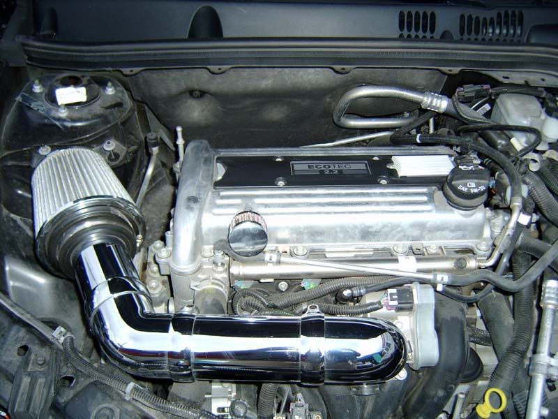
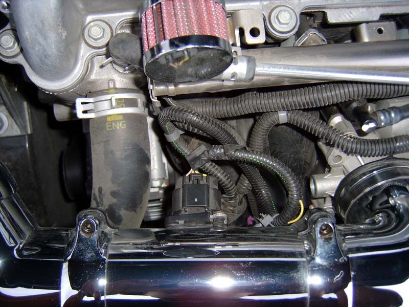
This one shows where the MAF is located:
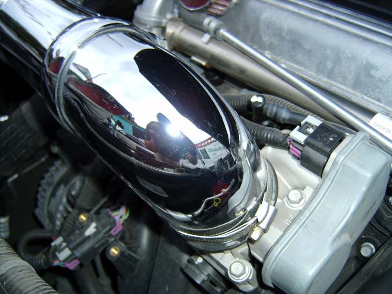
This shows the connection to the manifold, i used electrical tape....you can see it at the base:
This one shows where the MAF is located:
This shows the connection to the manifold, i used electrical tape....you can see it at the base:
Thread Starter
Member
Joined: 04-01-06
Posts: 346
Likes: 0
From: Castle Rock, Colorado
Originally Posted by Skottish
Here are the pictures of my install of this intake......
This one shows where the MAF is located:
This shows the connection to the manifold, i used electrical tape....you can see it at the base:
This one shows where the MAF is located:
This shows the connection to the manifold, i used electrical tape....you can see it at the base:
AWSOME LOOKS LIKE MINE!!!!!!
New Member
Joined: 06-20-06
Posts: 51
Likes: 0
From: gatineau,canada
Ok so its been a few days with install now...that teflon tape seems to shrink a bit with the heat, so now its a bit loose again. I have no fear of it falling off, but still sucks that it`s loose. I`m going to go buy one of those urethane couplers to fit it on the throttle body. Rubber should fit it much tighter that hard plastic. Everyone i show it too though can`t believe how good it looks for universal plastic.
I thought about the electrical tape, but figured with the heat on it, would probably gum it up pretty bad or somewhat melt and leak down the throttle body.
I`m not sure if the MAF there is going to throw you a code though. Usually they have to be pretty close to filter, as it is stock
I thought about the electrical tape, but figured with the heat on it, would probably gum it up pretty bad or somewhat melt and leak down the throttle body.
I`m not sure if the MAF there is going to throw you a code though. Usually they have to be pretty close to filter, as it is stock
New Member
Joined: 06-20-06
Posts: 51
Likes: 0
From: gatineau,canada
Originally Posted by Skottish
Here are the pictures of my install of this intake......
This one shows where the MAF is located:
This shows the connection to the manifold, i used electrical tape....you can see it at the base:
This one shows where the MAF is located:
This shows the connection to the manifold, i used electrical tape....you can see it at the base:
You should take that oil cap extension off your engine...Looks way better without
 . The oil cap by itself fits really good and has a rubber O-ring as well. Just pull the extension off and It`ll come right off.

Thread
Thread Starter
Forum
Replies
Last Post
OrangeCoba
Problems/Service/Maintenance
0
Sep 25, 2015 06:06 PM