How many of you 2.4 guys are running MAF only?
 09-16-2013, 07:17 PM
#1

How many of you 2.4 guys are running MAF only?
Did some MAF tuning today, debating on whether or not to run entirely on MAF or if i should tune the SD tables and set it back to use both all the way to redline. Not really certain how this will effect the performance with the VVT.
 09-16-2013, 08:03 PM
#2
You should tune the MAF fully anyway, and the PCM really only looks at the MAF unless you tell it otherwise. With a proper MAF tune the rest of the calculations will follow desired, so that's the best way to do it. VE is too dependent on other factors being constant and is mainly used as a logic check to make sure the MAF readings are in range.
Either way, changes you make will affect the VVT as listed, since it scrolls from Low-Mid-Hi tables based on MAP pressure by default.
Either way, changes you make will affect the VVT as listed, since it scrolls from Low-Mid-Hi tables based on MAP pressure by default.
09-16-2013, 08:27 PM
#3

You should tune the MAF fully anyway, and the PCM really only looks at the MAF unless you tell it otherwise. With a proper MAF tune the rest of the calculations will follow desired, so that's the best way to do it. VE is too dependent on other factors being constant and is mainly used as a logic check to make sure the MAF readings are in range.
Either way, changes you make will affect the VVT as listed, since it scrolls from Low-Mid-Hi tables based on MAP pressure by default.
Either way, changes you make will affect the VVT as listed, since it scrolls from Low-Mid-Hi tables based on MAP pressure by default.
09-16-2013, 09:00 PM
#4
You should tune the MAF fully anyway, and the PCM really only looks at the MAF unless you tell it otherwise. With a proper MAF tune the rest of the calculations will follow desired, so that's the best way to do it. VE is too dependent on other factors being constant and is mainly used as a logic check to make sure the MAF readings are in range.
Either way, changes you make will affect the VVT as listed, since it scrolls from Low-Mid-Hi tables based on MAP pressure by default.
Either way, changes you make will affect the VVT as listed, since it scrolls from Low-Mid-Hi tables based on MAP pressure by default.
09-17-2013, 12:55 PM
#5
MAP/baro are the same, but one is mounted on the manifold, one outside. VVT is MAP based.
Get the MAF dialed in and use it, it's more accurate than the VE tables anyway.
Dynamic airflow stock is set to reference both MAF and VE tables all the way to 7000rpm, now i was able to tune the maf up to 7k hz but since the stock settings reference both all the way to max even @ WOT, i was wondering if this is gonna wreak havoc with the VVT tables. I know it can be done with the LSJ pretty easily but with the VVT on the LE5 its a little different. Didnt want to hurt the car by leaving dynamic airflow disabled.
 09-17-2013, 07:45 PM
#7
Yeah i've made VVT changes on a turbo car (DFZ24's) and seen gains, earlier spool, better power up top. N/A VVT maps are not logical for a boosted car.
They are regulated by the manifold MAP sensor, I was mentioning the Baro because of a prior post, i've never messed with them. They are usually the exact same 1-bar sensor though, as an N/A 2.4. That's why we have to swap it for a 2/2.5/3 bar on a boost application.
They are regulated by the manifold MAP sensor, I was mentioning the Baro because of a prior post, i've never messed with them. They are usually the exact same 1-bar sensor though, as an N/A 2.4. That's why we have to swap it for a 2/2.5/3 bar on a boost application.
09-17-2013, 08:09 PM
#8
Senior Member

hmmmmmm I thought our VE was virtual and you cannot change it correctly ?
I have been dynamic airflow disabled for a long time (maf only) because of above ^
and Joe1 care to share a bit on vvt changes ? I have e-mail and donations ?
I have been dynamic airflow disabled for a long time (maf only) because of above ^
and Joe1 care to share a bit on vvt changes ? I have e-mail and donations ?
09-17-2013, 08:42 PM
#11
As far as i know the VVT tables go from 0-25, but where exactly would 0 be? Can we use negative numbers? I still havent been able to figure it out completely, im so used to using adjustable cam gears. I assumed that just going closer to 0 meant more overlap.
09-17-2013, 08:47 PM
#12
If you understand the adjustments and what you are changing you will be fine, it's amazing that a little cam retarding could change spool by several hundred rpm.
As mentioned above, you DON'T want the overlap once you are in boost, since it will only allow more cool charge air to blow out the back and drop EGT's the wrong way. If you focus on getting more air into the turbine before it spins up (timing and fuel, plus 'effective compression' from the cams) you can get that big puppy spinning way before 3K which is awesome for street manners.
09-18-2013, 07:56 AM
#13
Senior Member
iTrader: (17)
Join Date: 09-03-10
Location: motor city
Posts: 2,750
Likes: 0
Received 0 Likes
on
0 Posts
Although the actual numbers in the table can go a lot higher, 0 puts the cams in the fully retarded position and 25 puts the cams in the fully advanced position. No one actually knows where the no retard/no advance really is, I believe it is around 10 though.
09-21-2013, 07:25 PM
#15
Senior Member
iTrader: (17)
Join Date: 09-03-10
Location: motor city
Posts: 2,750
Likes: 0
Received 0 Likes
on
0 Posts
just get rid of overlap and advance down low, retard up top. Getting rid of the overlap really helped spool for me, I bet it would help you keep/hold more boost at a specific rev
09-22-2013, 09:20 AM
#17
Senior Member
iTrader: (17)
Join Date: 09-03-10
Location: motor city
Posts: 2,750
Likes: 0
Received 0 Likes
on
0 Posts
so you know what overlap is right?
I'm currently trying to figure out where our cams sit at when the VVT is doing nothing, aka the resting position. I'm not positive but I'm pretty sure there is some overlap at this position. Once this exact value in degrees is known, we can do some pretty simple math to figure out some minumum differences in the intake vs. exhaust cams to eliminate overlap. For now simply advance the exhaust (24* for example) and retard the intake a little bit so were pretty sure theres no overlap (17* for example). This setup would cut out 7* of overlap if there is any at the resting positions of the cams.
If anyone can read our specs and tell me how to fine the overlap I'd appreciate it
http://www.crateenginedepot.com/PDFS/ECS.pdf
09-23-2013, 09:20 PM
#18
Senior Member
Yes I know what overlap is.
What I'm asking is where and how do you see the overlap ?
I'm not doubting that there is some, just want to know ^^
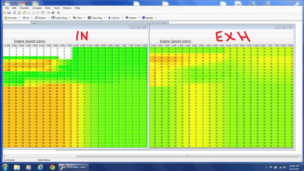
I'm just trying to understand the vvt tables, cause what little I know is the #'s in the below tables are just position #'s correct or are they degrees of advance and retard from the base cam position ? IDK, when I lost a intake sensor the intake cam parked at 0.
Cause the way I see it, is unless you know the degree difference of the intake close and exhaust open these number really don't show overlap, correct ?
Just trying to learn something before I make what I believe are needed changes.
What I'm asking is where and how do you see the overlap ?
I'm not doubting that there is some, just want to know ^^
I'm just trying to understand the vvt tables, cause what little I know is the #'s in the below tables are just position #'s correct or are they degrees of advance and retard from the base cam position ? IDK, when I lost a intake sensor the intake cam parked at 0.
Cause the way I see it, is unless you know the degree difference of the intake close and exhaust open these number really don't show overlap, correct ?
Just trying to learn something before I make what I believe are needed changes.
 09-23-2013, 10:27 PM
#19
Senior Member
iTrader: (17)
Join Date: 09-03-10
Location: motor city
Posts: 2,750
Likes: 0
Received 0 Likes
on
0 Posts
Yes I know what overlap is.
What I'm asking is where and how do you see the overlap ?
I'm not doubting that there is some, just want to know ^^
I'm just trying to understand the vvt tables, cause what little I know is the #'s in the below tables are just position #'s correct or are they degrees of advance and retard from the base cam position ? IDK, when I lost a intake sensor the intake cam parked at 0.
Cause the way I see it, is unless you know the degree difference of the intake close and exhaust open these number really don't show overlap, correct ?
Just trying to learn something before I make what I believe are needed changes.
Didn't mean to sound condescending or anything just asking so I should explain overlap or not.
Those look like stock cam tables, correct? Looking at the high airmass 3800 rpm sections, intake is advanced 24* and exhaust advanced 17*. This would mean 7* of overlap on top of whatever the resting position is.
If we can find the factory cam timing specs at rest we can then figure out how much timing difference we need to eliminate overlap.
09-24-2013, 12:06 AM
#21
If you look at that spike in those tables in the low throttle/rpm area, that's the car using the VVT to get EGR function, which is basically closing the exhaust cam super early and opening the intake super early, trapping some exhaust in the cyl. Gives you an idea of where the cams are in normal mode versus that EGR mode.

Thread
Thread Starter
Forum
Replies
Last Post