
How valve timing works

Thread Starter
I'm old school
Joined: 02-16-05
Posts: 6,905
Likes: 3
From: Nashville
How valve timing works
I have been wanting to make this thread for a long time now. I figure I'll at least get it started.
Here is a diagram of a generic 4 stroke engines valve timing;
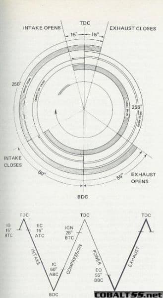
The top, round picture is in relation to crankshaft rotation. The bottom is in linear time. Both show the same thing in different ways. Use either one as a reference.
Let's start with the exhaust valve opening after combustion. In our example, it opens at 55 degrees BDC (bottom dead center) on the power stroke. At this point, the pressure from combustion has moved the piston as much as it is going to, so the valve opens and allows the gases to begin to exit the cylinder. First, the pressure of combustion starts the gases moving out. Then, the piston pushes gas out on the exhaust stroke. Lastly, inertia continues to move the gas out all the way up to 15 degree past TDC (top dead center). That, so far, is pretty easy.
Now lets look at the intake valve. You can see it opens at 15 degrees before TDC, even though the exhaust valve is still open. This is normal, and is called overlap. It does a number of good things. First, some of the fresh intake air goes right out with the exhaust. This help tremendously with cooling the exhaust valves. Second, the fresh air fills in the space remaining in the combustion chamber while the exhaust gas leaves. This helps with scavenging out the burnt gases, insuring a cylinder full of fresh air.
Once the exhaust valve closes, the intake charge is now drawn in almost the same way the exhaust was pushed out. First, via suction from the intake stroke. Then, via inertia after BDC all the way until 60 degrees after.
This diagram shows only valve timing. What it doesn't show is is valve lift. Cams can be ground to open the valves more or less, and can open and close the valves faster or slower depending on the "ramp" of the cam lobe. Those three things in total; timing, lift, and ramp, are what make up the statistics of your cam shafts.
With this intro to valve timing, you can probably start to see why different cams are desired for a N/A engine versus a forced induction engine.
I would LOVE to see a thread in the future that lists in side by side comparison these statistics of the stock cams in each of the Ecotec engines with their aftermarket replacements. That way we could all see what exactly is so different.
Here is a diagram of a generic 4 stroke engines valve timing;
The top, round picture is in relation to crankshaft rotation. The bottom is in linear time. Both show the same thing in different ways. Use either one as a reference.
Let's start with the exhaust valve opening after combustion. In our example, it opens at 55 degrees BDC (bottom dead center) on the power stroke. At this point, the pressure from combustion has moved the piston as much as it is going to, so the valve opens and allows the gases to begin to exit the cylinder. First, the pressure of combustion starts the gases moving out. Then, the piston pushes gas out on the exhaust stroke. Lastly, inertia continues to move the gas out all the way up to 15 degree past TDC (top dead center). That, so far, is pretty easy.
Now lets look at the intake valve. You can see it opens at 15 degrees before TDC, even though the exhaust valve is still open. This is normal, and is called overlap. It does a number of good things. First, some of the fresh intake air goes right out with the exhaust. This help tremendously with cooling the exhaust valves. Second, the fresh air fills in the space remaining in the combustion chamber while the exhaust gas leaves. This helps with scavenging out the burnt gases, insuring a cylinder full of fresh air.
Once the exhaust valve closes, the intake charge is now drawn in almost the same way the exhaust was pushed out. First, via suction from the intake stroke. Then, via inertia after BDC all the way until 60 degrees after.
This diagram shows only valve timing. What it doesn't show is is valve lift. Cams can be ground to open the valves more or less, and can open and close the valves faster or slower depending on the "ramp" of the cam lobe. Those three things in total; timing, lift, and ramp, are what make up the statistics of your cam shafts.
With this intro to valve timing, you can probably start to see why different cams are desired for a N/A engine versus a forced induction engine.
I would LOVE to see a thread in the future that lists in side by side comparison these statistics of the stock cams in each of the Ecotec engines with their aftermarket replacements. That way we could all see what exactly is so different.
Last edited by Halfcent; Sep 14, 2007 at 08:38 PM.


 Keep up the good work!


Member
Joined: 05-18-07
Posts: 288
Likes: 0
From: Bloomington, IL
Constant VVT?
I have been wanting to make this thread for a long time now. I figure I'll at least get it started.
Here is a diagram of a generic 4 stroke engines valve timing;
The top, round picture is in relation to crankshaft rotation. The bottom is in linear time. Both show the same thing in different ways. Use either one as a reference.
Let's start with the exhaust valve opening after combustion. In our example, it opens at 55 degrees BDC (bottom dead center) on the power stroke. At this point, the pressure from combustion has moved the piston as much as it is going to, so the valve opens and allows the gases to begin to exit the cylinder. First, the pressure of combustion starts the gases moving out. Then, the piston pushes gas out on the exhaust stroke. Lastly, inertia continues to move the gas out all the way up to 15 degree past TDC (top dead center). That, so far, is pretty easy.
Now lets look at the intake valve. You can see it opens at 15 degrees before TDC, even though the exhaust valve is still open. This is normal, and is called overlap. It does a number of good things. First, some of the fresh intake air goes right out with the exhaust. This help tremendously with cooling the exhaust valves. Second, the fresh air fills in the space remaining in the combustion chamber while the exhaust gas leaves. This helps with scavenging out the burnt gases, insuring a cylinder full of fresh air.
Once the exhaust valve closes, the intake charge is now drawn in almost the same way the exhaust was pushed out. First, via suction from the intake stroke. Then, via inertia after BDC all the way until 60 degrees after.
This diagram shows only valve timing. What it doesn't show is is valve lift. Cams can be ground to open the valves more or less, and can open and close the valves faster or slower depending on the "ramp" of the cam lobe. Those three things in total; timing, lift, and ramp, and what make up the statistics of your cam shafts.
With this intro to valve timing, you can probably start to see why different cams are desired for a N/A engine versus a forced induction engine.
I would LOVE to see a thread in the future that lists in side by side comparison these statistics of the stock cams in each of the Ecotec engines with their aftermarket replacements. That way we could all see what exactly is so different.
Can you provide a link to how GM does constant Variable Valve Timing? As I understand it, the cam face has a low end profile on one side (end) and a high end profile on the other. As the engine RPMs increase, the cam shaft is laterally shifted hydraulically with respect to the rocker arms towards the high end profile. I also understand that only the LE5 and LNF heads and cams use this method of VVT. So can one convert a 2.4L NA to direct injection by swapping to LNF heads? I wonder what kind of HP one could produce NA with tuning of the 2.4L Direct Injection.....
Member
Joined: 05-18-07
Posts: 288
Likes: 0
From: Bloomington, IL
But I do not understand how Direct Injection can be done via the Block as you state as gasoline is injected into the cylinder while both valves are closed ; every thing I've read so far regarding GM Direct Injection compares it to a Diesel engine's injection system (on which I'm school trained {and Honor Graduate}).
At any rate Direct Injection along with CVVT seems to provide great opportunities for both power and economy depending of course on ECU programming and throttle position.


Senior Member
Joined: 12-01-06
Posts: 803
Likes: 0
From: Leavittsburg, Ohio
Thread Starter
I'm old school
Joined: 02-16-05
Posts: 6,905
Likes: 3
From: Nashville
Wait, NJHK told you that the LNF injectors are mounted in the block? That's surprising, because it's wrong. It is most certainly mounted in the head. Here is a picture:

The VVT works by changing the cam timing, not by shifting the cam left and right to a different lobe profile. It has a hydraulic adjustable timing gear. Additionally, the high pressure fuel pump is not driven off a chain. It is cam driven. In your picture, it's in in the upper right corner attached to the intake cam.
The VVT works by changing the cam timing, not by shifting the cam left and right to a different lobe profile. It has a hydraulic adjustable timing gear. Additionally, the high pressure fuel pump is not driven off a chain. It is cam driven. In your picture, it's in in the upper right corner attached to the intake cam.
Last edited by Halfcent; Sep 15, 2007 at 10:39 AM.
Member
Joined: 05-18-07
Posts: 288
Likes: 0
From: Bloomington, IL
Wait, NJHK told you that the LNF injectors are mounted in the block? That's surprising, because it's wrong. It is most certainly mounted in the head. Here is a picture:
The VVT works by changing the cam timing, not by shifting the cam left and right to a different lobe profile. It has a hydraulic adjustable timing gear. Additionally, the high pressure fuel pump is not driven off a chain. It is cam driven. In your picture, it's in in the upper right corner attached to the intake cam.
The VVT works by changing the cam timing, not by shifting the cam left and right to a different lobe profile. It has a hydraulic adjustable timing gear. Additionally, the high pressure fuel pump is not driven off a chain. It is cam driven. In your picture, it's in in the upper right corner attached to the intake cam.
Excellent thread discussion! I for one enjoyed learning exactly how the Constant Variable Valve Timing of my 2.4L LE5 engine works. Thanks!
Premium Member
Joined: 07-04-05
Posts: 730
Likes: 1
From: No where man
The VVT system used on most GM DOHC engines such as the LE5 Cobalts (and similar to the aformentioned Northstar) use a Vane type cam phasing mechanism that can control each cam through a range of approx 25 degrees.
The Vane Phaser is controlled the same way as a splined phaser, through a control valve, but internally its components are very different. Instead of using an internal piston with helical splines, a rotor with four vanes is connected to the end of the camshaft. The rotor is housed inside of the stator that is bolted to the cam gear.
The rotor and stator are not linked mechanically together as in the splined phaser. Instead, oil pressure is controlled on both sides of the vanes of the rotor, creating a hydraulic link to the stator. By varying the balance of oil pressure on either side of the vanes, the position of the camshaft can be controlled. A return spring is also incorporated under the reluctor of the phaser to help return it to a 0� (home) position where the exhaust cam is fully advanced and the intake cam fully retarded.
You can see the vane phaser mechnism in the LNF artwork above, and below is another pic showing some of the vane phaser features
During start-up, when little oil pressure is available, an internal spring-loaded locking pin keeps the rotor and stator locked together in the home position. When phasing is desired, oil pressure is applied to the phaser, unlocking the pin and approx 25� cam advance/retard can be achieved. Besides basic "event" timing this allows for variable overlap levels for improved emissions, economy and power.
HTH
Regards
WopOnTour
Last edited by WopOnTour; Oct 1, 2007 at 11:20 PM.
Senior Member
Joined: 08-20-07
Posts: 2,061
Likes: 0
From: Irwin, Pa (S of Pittsburgh)
this is great info. i never really understood how valve timing worked, just how i was supposed to adjust it with doing certain mods. where do you acquire this info from???
and my friend is turboing his lt and was wondering how he should adjust the timing best. hes basically going with the hahn kit but a different turbo, injectors, and hes buying the sct livewire but tuning it himself (idk why i told him just go with the hahn kit but he wont tell me). So how exactly would it work with turbocharging the engine, like do you keep timing the same or adjust it to help spool?
and my friend is turboing his lt and was wondering how he should adjust the timing best. hes basically going with the hahn kit but a different turbo, injectors, and hes buying the sct livewire but tuning it himself (idk why i told him just go with the hahn kit but he wont tell me). So how exactly would it work with turbocharging the engine, like do you keep timing the same or adjust it to help spool?

Premium Member
Joined: 07-04-05
Posts: 730
Likes: 1
From: No where man
Oh and by the way, the 2.0LNF is going to FINALLY find it's way into the 2008 HHR SS later this year (Q:4 2007)
AND
The current .19 BETA version of HPT is capapble of tuning the LNF
(another cool tuning feature is the LNF comes from factory using WBO2)
Wop
AND
The current .19 BETA version of HPT is capapble of tuning the LNF
(another cool tuning feature is the LNF comes from factory using WBO2)
Wop
Last edited by WopOnTour; Sep 17, 2007 at 03:03 AM.
Member
Joined: 05-18-07
Posts: 288
Likes: 0
From: Bloomington, IL
Actually the "helical spline" type cam phaser is used more on the pushrod engines (and the 4.2L inline)
The VVT system used on most GM DOHC engines such as the LE5 Cobalts (and similar to the aformentioned Northstar) use a Vane type cam phasing mechanism that can control each cam through a range of approx 25 degrees.
The Vane Phaser is controlled the same way as a splined phaser, through a control valve, but internally its components are very different. Instead of using an internal piston with helical splines, a rotor with four vanes is connected to the end of the camshaft. The rotor is housed inside of the stator that is bolted to the cam gear.
The rotor and stator are not linked mechanically together as in the splined phaser. Instead, oil pressure is controlled on both sides of the vanes of the rotor, creating a hydraulic link to the stator. By varying the balance of oil pressure on either side of the vanes, the position of the camshaft can be controlled. A return spring is also incorporated under the reluctor of the phaser to help return it to a 0� (home) position where the exhaust cam is fully advanced and the intake cam fully retarded.
You can see the vane phaser mechnism in the LNF artwork above, and below is another pic showing some of the vane phaser features
During start-up, when little oil pressure is available, an internal spring-loaded locking pin keeps the rotor and stator locked together in the home position. When phasing is desired, oil pressure is applied to the phaser, unlocking the pin and approx 25� cam advance/retard can be achieved. Besides basic "event" timing this allows for variable overlap levels for improved emissions, economy and power.
HTH
Regards
WopOnTour
Premium Member
Joined: 07-04-05
Posts: 730
Likes: 1
From: No where man
Wop

Thread
Thread Starter
Forum
Replies
Last Post
09BlkCrusader
Parts
30
Sep 9, 2015 04:47 PM
Getaway_Driver
Problems/Service/Maintenance
41
Sep 8, 2015 09:41 AM