
Street Dreamz OFFICIAL big ass turbo build thread...

Thread Starter
Banned
Joined: 02-23-06
Posts: 1,287
Likes: 0
From: Mo-town, WV
Street Dreamz OFFICIAL big ass turbo build thread...
This thread will probably become overloaded with pictures and words over the next month or so. Bear in mind if you don't have cable net or at least dial up, you're probably best off to just look at it from someone's computer who does lol. I'll start with a few details about the more complicated stuff I need to do and fill in the little things as I go.
In short I have finally settled on a turbo, fuel pump, piping route, tuning software, and horsepower goals. I decided to go with a Borg Warner Airwerks S200 mainly because of it's twin scroll design which gives me several advantages over just a standard ball bearing turbo. First off the twin scroll design allows for me to split the exhaust pulses and decrease spool time by a huge margin over a standard turbo. The decrease in exhaust pressure also helps in using a smaller wastegate spring to keep the wastegates closed, which is helpful for the MSD LBC solenoids to modulate boost pressure on the launch. Also it means I don't have to run CO2 to keep them closed and modulate with the solenoids. The downside to this means I have to build my own manifold, which is not a problem really since I can use pretty standard steel to do it with as the twin scroll design will also lower EGTs. Having full race make me a custom manifold I found out runs an easy $2,500 and at least a month. Here are some crude pictures of the routing for header to the turbo:

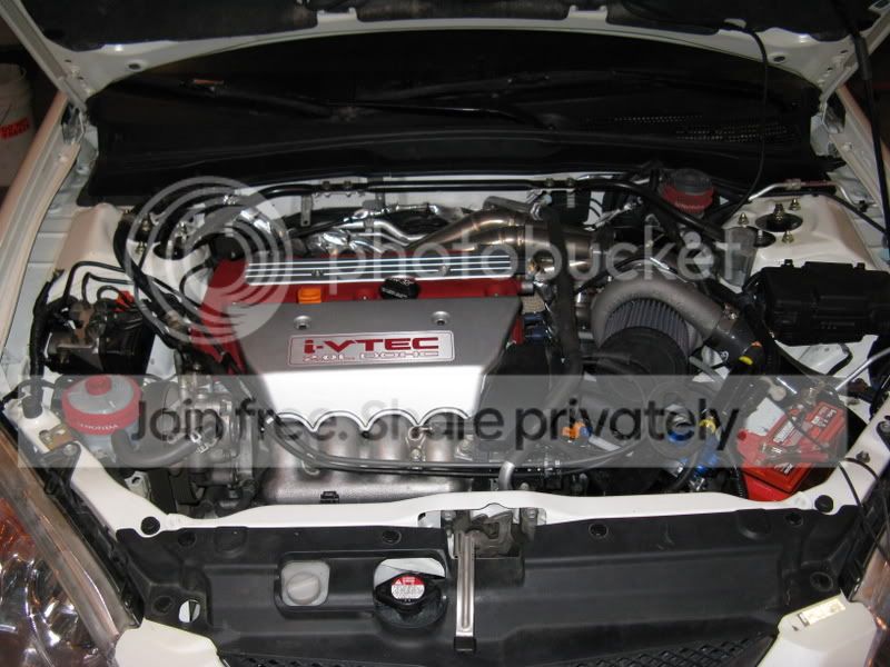
Above I have circled the brake/clutch fluid resovoir (yes they share the same one), the fuse/relay box and PCM, the brake module, and the coolant overflow tank. The coolant overflow tank will end up on the other side of the engine here:

The fluid resovoir will be relocated all the way against the driver's side strut tower. The fusebox is going to go where the coolant overflow was. The PCM will be relocated to behind where the fusebox is sitting right now, all the way against the firewall. The brake module will then be moved over about 6 inches to your visual left, then down about a foot and mounted to the front driver's side frame rail, similar to where the air filter sits now. After having moved all that there is TONS of room between the transmission and the hood and the driver's strut tower and the head. But why you ask? To make room for the turbo....

Like I said it's a pretty crude drawing right now, but you get the idea. Basically the manifold runners will curve out from the engine in clean sweeps and head up over the valve cover (there's plenty of room) then a somewhat steep down then up curve into the bottom of the turbine housing with the two wastegates mounted right there below the turbine inlet housing. The turbine housing will exit with 3" piping down below back towards where the factory 2.75" downpipe is running now. The turbo's intake piping will run down back behind the transmission and towards the ground. The charge piping will run pretty much straight out from the front of the turbo's outlet facing the front of the car and down through the fender well to the inlet of the intercooler. Then from out of the intercooler it will pass into the passenger fenderwell, around behind the radiator, and curve up into the throttle body/custom sheet metal intake manifold. There is so much room between the block and radiator because GM had to make room for the blower and the huge ass intake manifold that has the intercooler for the heat exchanger built into it. It's a big boy. That's all for now. Check back soon!!!
In short I have finally settled on a turbo, fuel pump, piping route, tuning software, and horsepower goals. I decided to go with a Borg Warner Airwerks S200 mainly because of it's twin scroll design which gives me several advantages over just a standard ball bearing turbo. First off the twin scroll design allows for me to split the exhaust pulses and decrease spool time by a huge margin over a standard turbo. The decrease in exhaust pressure also helps in using a smaller wastegate spring to keep the wastegates closed, which is helpful for the MSD LBC solenoids to modulate boost pressure on the launch. Also it means I don't have to run CO2 to keep them closed and modulate with the solenoids. The downside to this means I have to build my own manifold, which is not a problem really since I can use pretty standard steel to do it with as the twin scroll design will also lower EGTs. Having full race make me a custom manifold I found out runs an easy $2,500 and at least a month. Here are some crude pictures of the routing for header to the turbo:
Above I have circled the brake/clutch fluid resovoir (yes they share the same one), the fuse/relay box and PCM, the brake module, and the coolant overflow tank. The coolant overflow tank will end up on the other side of the engine here:
The fluid resovoir will be relocated all the way against the driver's side strut tower. The fusebox is going to go where the coolant overflow was. The PCM will be relocated to behind where the fusebox is sitting right now, all the way against the firewall. The brake module will then be moved over about 6 inches to your visual left, then down about a foot and mounted to the front driver's side frame rail, similar to where the air filter sits now. After having moved all that there is TONS of room between the transmission and the hood and the driver's strut tower and the head. But why you ask? To make room for the turbo....
Like I said it's a pretty crude drawing right now, but you get the idea. Basically the manifold runners will curve out from the engine in clean sweeps and head up over the valve cover (there's plenty of room) then a somewhat steep down then up curve into the bottom of the turbine housing with the two wastegates mounted right there below the turbine inlet housing. The turbine housing will exit with 3" piping down below back towards where the factory 2.75" downpipe is running now. The turbo's intake piping will run down back behind the transmission and towards the ground. The charge piping will run pretty much straight out from the front of the turbo's outlet facing the front of the car and down through the fender well to the inlet of the intercooler. Then from out of the intercooler it will pass into the passenger fenderwell, around behind the radiator, and curve up into the throttle body/custom sheet metal intake manifold. There is so much room between the block and radiator because GM had to make room for the blower and the huge ass intake manifold that has the intercooler for the heat exchanger built into it. It's a big boy. That's all for now. Check back soon!!!


Senior Member
Joined: 08-13-05
Posts: 5,733
Likes: 1
From: the glove
this set up screams....
inefficiency FTW!!!!!!!!!!!!
pressure, HEAT, velocity....your 3 biggest concerns are all but forgotten with a set up such as this.
have fun moving all that stuff around, i wish you luck.
inefficiency FTW!!!!!!!!!!!!
pressure, HEAT, velocity....your 3 biggest concerns are all but forgotten with a set up such as this.
have fun moving all that stuff around, i wish you luck.
Senior Member
Joined: 08-13-05
Posts: 5,733
Likes: 1
From: the glove
looks allot like a 35r on a RSX.
theres a guy round here running a 35-81R at a whooping 8psi...most inefficient set up of all time (low boost, big turbo) but it makes good power, dont think it ever "spools" tho, the power curve never "jumps" but its cool to look at.
theres a guy round here running a 35-81R at a whooping 8psi...most inefficient set up of all time (low boost, big turbo) but it makes good power, dont think it ever "spools" tho, the power curve never "jumps" but its cool to look at.


Senior Member
Joined: 10-01-06
Posts: 5,134
Likes: 0
From: Maidstone, SK
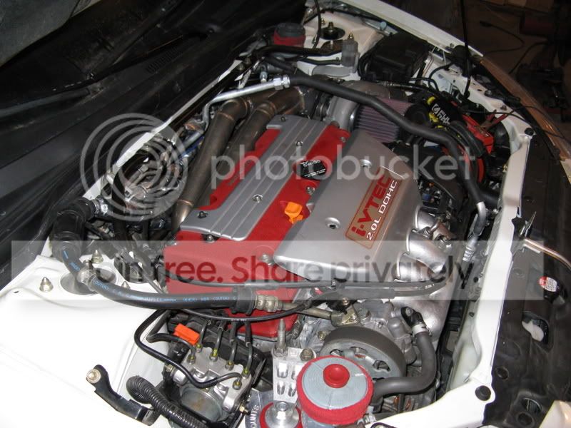
I'm pretty sure it's a Garret T3/T04E.
I just posted the pictures so we could all get a good look at the goofy header involved.
Senior Member
Joined: 07-08-05
Posts: 6,200
Likes: 0
From: Niceville, FL
I like the innovative idea for sure. Good luck moving all that stuff and on the project. I just prefer to keep all the hot stuff a bit lower than where you're mounting you stuff. Either way, I can't wait to see the results.
Senior Member
Joined: 10-01-06
Posts: 5,134
Likes: 0
From: Maidstone, SK
Nope... I messaged the guy who owns it... T3/TO4E.
http://cheapturbo.stores.yahoo.net/peacrsxcotuk.html

Thread
Thread Starter
Forum
Replies
Last Post