When you click on links to various merchants on this site and make a purchase, this can result in this site earning a commission. Affiliate programs and affiliations include, but are not limited to, the eBay Partner Network.
Here are simple directions to install the N2MB WOT BOX on an lnf. There directions are only for LSJ cobalt's.
What you need: Socket wrench, 10mm socket, Wire strippers, razor blade, heat gun, Pocket screwdriver, Common sense.
STEP1: disconnect the battery (+or- doesnt matter)
Step 2: Get a wire hanger and poke a hole through the grommet in the fire wall from the engine bay side , then go on the inside of the car and pull it in a little more. Then tape the wires to the hanger and pull through firewall.
Step 3: Strip ends of wire's and run them however you would like.
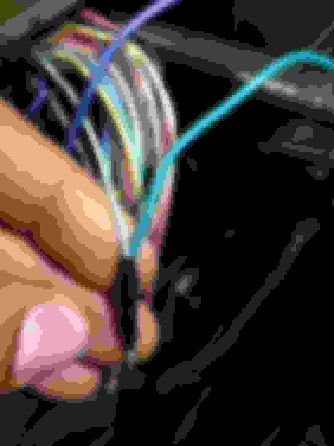
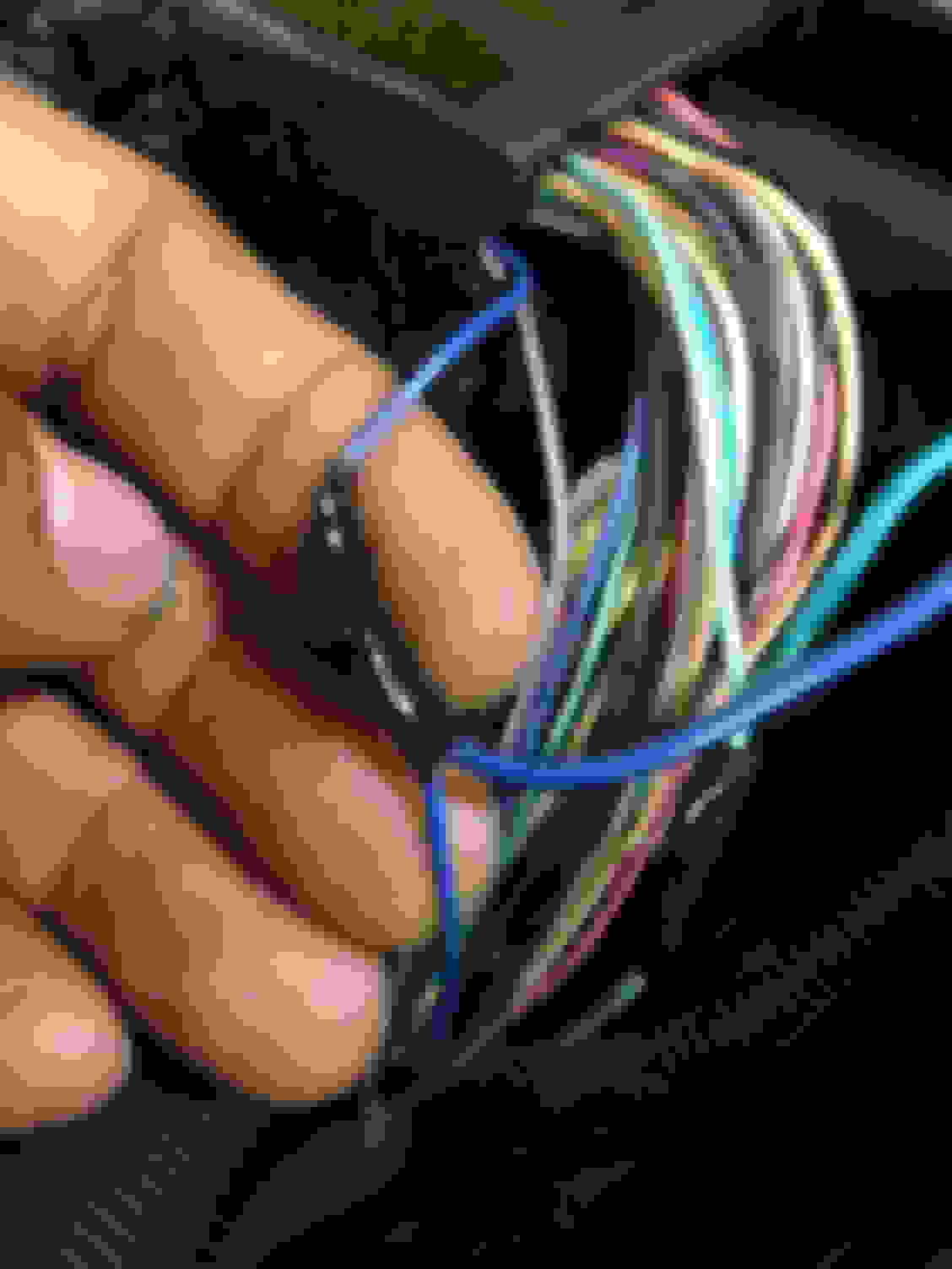
Step 4: Disconnect the two connectors from your PCM, and Remove the top cover/locking hinge covering the wires using the pocket screwdriver.
Step 5: Strip and Twist both the Green and Blue wire ends and set aside, Then you need to count the pins.
Take the green wire coming from the WOT BOX and splice then connect it to The Light Green wire (pin#37 see below)
Pin#37 (small connector) (LIGHT GREEN) is your CPP (clutch pedal posittion)
Now for the blue wire.
Take the Blue wire coming from the WOT BOX and connect it to the Dark Blue wire pin #15 (see Below)
Pin #15 (small connector) (Dark Blue) is your accellerator pedal position.
Its your decision between electrical tape or shrink wrap.
make sure to pull the wire looms off to splice the wire further back from the connector.
Step 6: Now take the yellow wire and strip the end and set aside. Remove the top cover / locking hanger from the large PCM connector.
Count the pins and find pin #55 ( purple wire)
pin#55 (large connector) PURPLE is your Rpm/ ignition signal
Splice the purple wire and connect the yellow wire to it.
tape it up and thats the only wire that needs to be connected in this step.
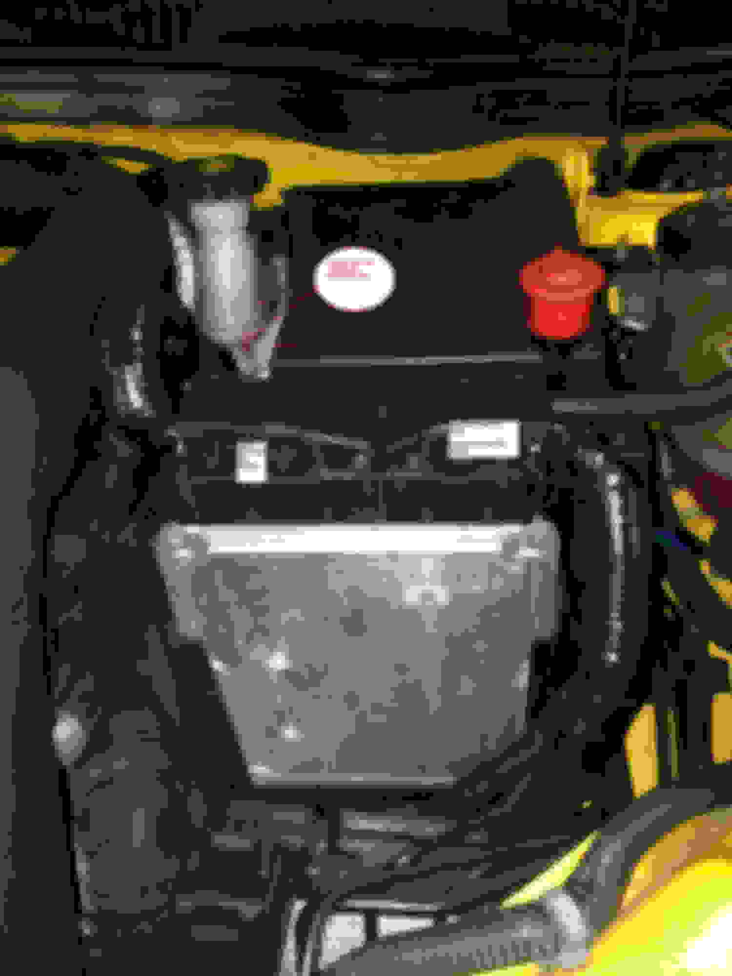
Step 7: locate the set of ignition wires coming out of the fuse box (toward passnger side) and remove the wire loom.
Locate the Pink and white wire and cut it in half and strip both ends.
Connect the red wire coming from the wot box to the wire that is closest to the fuse box and the orange wire connects to the pink/white wire that you have left over after cutting it in half.
Step 8: Take the Connector provided in the kit and stip the black ground wire and crimp it to the end. i used a bolt on the clutch pedal for my ground .
Next run the harness up into the Compartment to the left of the steering wheel and connect the WOT BOX .
thats it. for the install.
once it is install Refer to the N2MB website's direction for testing the WOT BOX to assure that everything is working as it should.
here is a Map of where all the wires need to do besides the ground
Wow this is perfect Bananna greatly appreciated for all your work and pics, this is great for me as I am running a standalone harness for the LNF that does not have LNS or a 2 step. This makes things super easy for me.
Since you are actually creating another ignition circuit through the wot box, it would be handy to have the ability to completely remove it from the circuit entirely if ever needed without having to splice and solder the ignition wire again. And it is as simple as changing a fuse.
I pulled off the entire fuse box so I could trace the ignition coil wire. I found it lead directly underneath fuse "INJ IGN MDL 15a". One side of the fuse for orange wire and other side of fuse for red wire. THIS IS FOR HHR LNF, not sure if that's the fuse for cobalt, but same idea. If you know how to use a multimeter you can figure it out. You will have to remove all fuses and relays to figure out which wire goes to which fuse with continuity tests.
If you do the install this way, then you have to remove the fuse from fuse box that you wired the red and orange wires to. Since you have to remove the "INJ IGN MDL 15a" fuse to make wot box functional You will need to wire in a 15amp inline fuse in this circuit on the coil side to retain circuit protection.
This is allot better way to do this as if you ever had trouble with the wot box you just plug the fuse back in and your good to go
Probably not anyone on here anymore but just to make sure this is for the LNF turbo cobalt correct? I've just been having trouble figuring out how to hook up my WOT box to my Cobalt.
So I just recently installed a wot box to my Lnf like 3 days ago. I made sure to follow the steps from this thread carefully, but I ended up running into problems.
Problems:
- Getting a message that says : � Engine power reduced�
- My exhaust sounds like a whole motorcycle when it�s idle in neutral
I am just posting this here , to hopefully get any feedback from people who might have an idea on what can possibly cause these problems or have ran into these problems too
i would really appreciate it , if you guys can leave any ideas on what it�s Causing my problems
Reviving a 5 year old thread my apologies. In the RPM section of my wot box software, it says my RPM is at 35971 at all times. Im wired in correctly, so im not sure what the issue is. Please help