
2.2 LAP Engine: N2MB LAP Installation Instructions


Thread Starter
Senior Member
iTrader: (1)
Joined: 11-16-10
Posts: 1,191
Likes: 0
From: Chicago/ NW Burbs
N2MB LAP Installation Instructions
Hey guys, so I recently installed my N2MB 2 step and I decided to do this write up because I had a hard time finding the correct information to install this on the LAP engines. I did quite a bit of research so I hope this helps!
Tools:
Soldering iron
Solder
Electrical tape
Heat shrink
Razor blade
Wire strippers
Ring Connector
BEFORE ANYTHING! PLEASE DISCONNECT NEGATIVE SIDE OF BATTERY TERMINAL!
Step 1
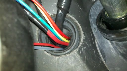
Take the all of the wires EXCEPT the Black 18 gauge wire and run them through the grommet in our firewall.
Step 2
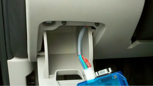
Feed the connector side of the N2MB harness up to the pull out tray on the driver side compartment.
Feel free to locate that anywhere else, I found it convenient here so I can pull it out and see if the LED's are still lighting up to make sure it's working properly.
Step 3
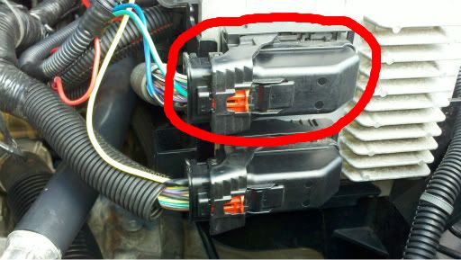
Run your blue, green, and yellow wire by the ECM and locate the X1 ECM connector. The X1 connector is the top connector on the actual computer.
Step 4
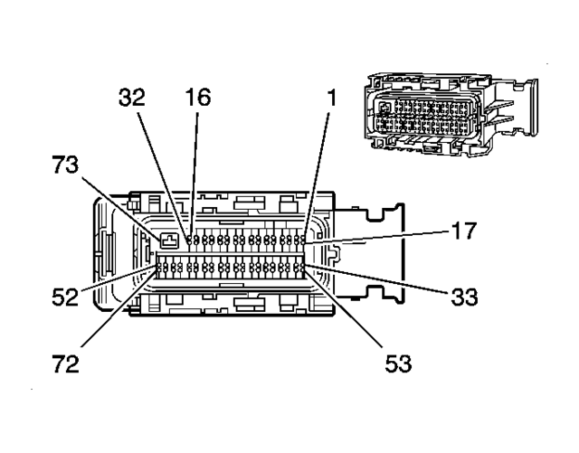
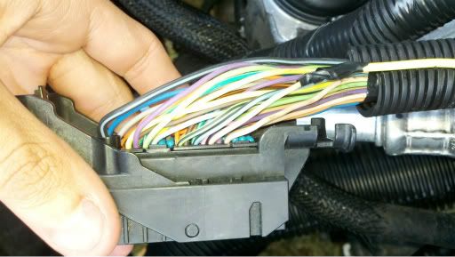
Disconnect the X1 connector and locate the Accelerator Pedal Position(APP) Sensor Signal Wire. It is a DARK BLUE wire and is in Pin 1
Step 5
Strip away some of the insulation on the BLUE APP Wire coming out of the X1 Connector then strip the end of the BLUE 2 step wire. Once both wires are exposed solder the 2 wires together and cover connection with electrical tape.
Step 6
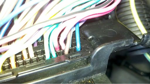
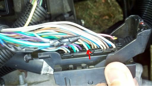
On the same X1 Connector find the LIGHT GREEN wire in the pin 61 spot. This wire is the Clutch Pedal Position(CPP) sensor and will connect to the GREEN wire from the 2 step harness. Use the first picture from step 4 to locate Pin 61.
The wire is the LIGHT GREEN wire that has an empty space to the left and right of it. It is on the bottom row of pins.
Step 7
Strip away some of the insulation on the LIGHT GREEN CPP wire coming from the X1 Connector then strip the end of the GREEN wire from the 2 step harness. Once both wires are exposed, solder them together and cover the connection with electrical tape.
Step 8
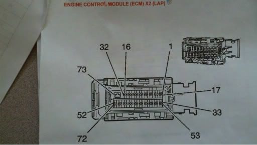
Plug the X1 Connector back into its socket and unplug the X2 Connector, the one right below. On the X2 Connector find the Fuel Injector 1 Control wire. It is a TAN colored wire and is in pin 6.
Step 9
Once the TAN Fuel Injector 1 Control wire is found, strip back some of the insulation then strip the end of the YELLOW wire off the 2 step harness and solder together. Once solder cover the connection with electrical tape. Plug in the connector to the ECM then put the cover back on.
Step 10
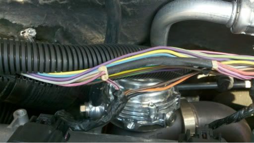
After those 3 wires, you are left with the RED/RED and BLACK wires. These 2 wires attach to the Ignition Coil Controls. In order to find the right wire, located the Ignition Coil harness on top of the valve cover.
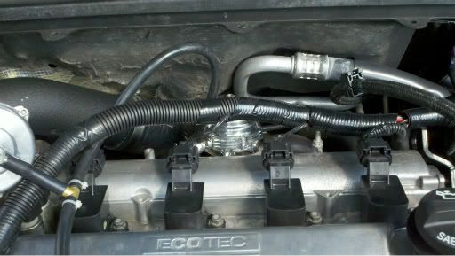
Each Ignition Coil has a pink/black wire coming out of it. These four wires are connected together by a PINK/WHITE Wire that runs to the Ignition Control Fuse. To find this wire cut away the electrical tape around the split loom and follow the pink/black wires to where they connect too.
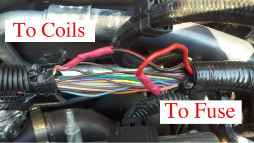
Step 11
Cut the PINK/WHITE Wire and split both ends and place a piece of heat shrink on each side of the wire. Peel apart the RED/RED and BLACK wires and strip both ends. The RED and BLACK Wire connects to the end of the PINK/WHITE Wire coming from the Ignition Coils. The RED Wire connects to the end of the PINK/WHITE wire that goes to fuse. Solder both connections appropriately then slide the heat shrink over the exposed wires and apply heat either with your soldering iron or another form of heat.
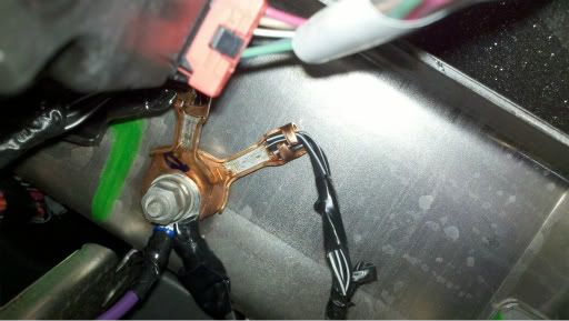
Step 12
Now that everything in the engine bay is done, clean up and put everything back together and then find your black wire under your steering wheel. Strip the end of the black wire and connect it to a ring connector. Once that is connected, find a ground by the steering column and connect it.
At this point all wires should be connected correctly. All that's left is for you to connect your battery and clean up.
Testing the WOT Box
www2
MAKE SURE YOU HAVE NO LIFT SHIFT ENABLED TO TEST! ALSO, DOWNLOAD THE NEWEST FIRMWARE BY USING THE N2MB USER INTERFACE.
Key on the car but do not start the engine. Press the gas pedal to the floor. You should see the LED on the WOT Box start to rapidly blink. If it does not, check your APP signal connection(WOT Box BLUE wire).
Next, with the gas pedal still fully depressed, press the clutch pedal to the floor. You should see the LED on the WOT Box briefly go out, and then come back on solid for one second and then finally resume blinking rapidly. If you do not see this, check your Clutch Pedal Position Switch signal connection (WOT Box GREEN wire).
Next, start the engine. Quickly press the gas pedal to the floor and immediately step on the clutch. You should hear the engine start to rev up, stumble for a short period while the ignition and fuel is cut, then return back on and continue rev'ing. Remove your foot from the gas before you hit the rev limiter. The 2-step will not engage if the gas is depressed before the clutch. This is normal. If the engine does not stumble or pause when the LED turns out, then check the WOT Box RED / BLACK paired wires. Verify that the RED and BLACK 16 AWG are wired facing the proper way. If they are reversed, the ignition cut will not work.
Lastly, test the 2-Step. Press the clutch pedal down and then press the gas pedal all the way down. The engine should rev up to the desired RPM and hold. If it does not, be sure to remove your foot from the gas before you hit the rev limiter. If the 2-step does not work, check the Ignition coil control signal (WOT Box YELLOW wire)
Tools:
Soldering iron
Solder
Electrical tape
Heat shrink
Razor blade
Wire strippers
Ring Connector
BEFORE ANYTHING! PLEASE DISCONNECT NEGATIVE SIDE OF BATTERY TERMINAL!
Step 1
Take the all of the wires EXCEPT the Black 18 gauge wire and run them through the grommet in our firewall.
Step 2
Feed the connector side of the N2MB harness up to the pull out tray on the driver side compartment.
Feel free to locate that anywhere else, I found it convenient here so I can pull it out and see if the LED's are still lighting up to make sure it's working properly.
Step 3
Run your blue, green, and yellow wire by the ECM and locate the X1 ECM connector. The X1 connector is the top connector on the actual computer.
Step 4
Disconnect the X1 connector and locate the Accelerator Pedal Position(APP) Sensor Signal Wire. It is a DARK BLUE wire and is in Pin 1
Step 5
Strip away some of the insulation on the BLUE APP Wire coming out of the X1 Connector then strip the end of the BLUE 2 step wire. Once both wires are exposed solder the 2 wires together and cover connection with electrical tape.
Step 6
On the same X1 Connector find the LIGHT GREEN wire in the pin 61 spot. This wire is the Clutch Pedal Position(CPP) sensor and will connect to the GREEN wire from the 2 step harness. Use the first picture from step 4 to locate Pin 61.
The wire is the LIGHT GREEN wire that has an empty space to the left and right of it. It is on the bottom row of pins.
Step 7
Strip away some of the insulation on the LIGHT GREEN CPP wire coming from the X1 Connector then strip the end of the GREEN wire from the 2 step harness. Once both wires are exposed, solder them together and cover the connection with electrical tape.
Step 8
Plug the X1 Connector back into its socket and unplug the X2 Connector, the one right below. On the X2 Connector find the Fuel Injector 1 Control wire. It is a TAN colored wire and is in pin 6.
Step 9
Once the TAN Fuel Injector 1 Control wire is found, strip back some of the insulation then strip the end of the YELLOW wire off the 2 step harness and solder together. Once solder cover the connection with electrical tape. Plug in the connector to the ECM then put the cover back on.
Step 10
After those 3 wires, you are left with the RED/RED and BLACK wires. These 2 wires attach to the Ignition Coil Controls. In order to find the right wire, located the Ignition Coil harness on top of the valve cover.
Each Ignition Coil has a pink/black wire coming out of it. These four wires are connected together by a PINK/WHITE Wire that runs to the Ignition Control Fuse. To find this wire cut away the electrical tape around the split loom and follow the pink/black wires to where they connect too.
Step 11
Cut the PINK/WHITE Wire and split both ends and place a piece of heat shrink on each side of the wire. Peel apart the RED/RED and BLACK wires and strip both ends. The RED and BLACK Wire connects to the end of the PINK/WHITE Wire coming from the Ignition Coils. The RED Wire connects to the end of the PINK/WHITE wire that goes to fuse. Solder both connections appropriately then slide the heat shrink over the exposed wires and apply heat either with your soldering iron or another form of heat.
Step 12
Now that everything in the engine bay is done, clean up and put everything back together and then find your black wire under your steering wheel. Strip the end of the black wire and connect it to a ring connector. Once that is connected, find a ground by the steering column and connect it.
At this point all wires should be connected correctly. All that's left is for you to connect your battery and clean up.
Testing the WOT Box
www2
MAKE SURE YOU HAVE NO LIFT SHIFT ENABLED TO TEST! ALSO, DOWNLOAD THE NEWEST FIRMWARE BY USING THE N2MB USER INTERFACE.
Key on the car but do not start the engine. Press the gas pedal to the floor. You should see the LED on the WOT Box start to rapidly blink. If it does not, check your APP signal connection(WOT Box BLUE wire).
Next, with the gas pedal still fully depressed, press the clutch pedal to the floor. You should see the LED on the WOT Box briefly go out, and then come back on solid for one second and then finally resume blinking rapidly. If you do not see this, check your Clutch Pedal Position Switch signal connection (WOT Box GREEN wire).
Next, start the engine. Quickly press the gas pedal to the floor and immediately step on the clutch. You should hear the engine start to rev up, stumble for a short period while the ignition and fuel is cut, then return back on and continue rev'ing. Remove your foot from the gas before you hit the rev limiter. The 2-step will not engage if the gas is depressed before the clutch. This is normal. If the engine does not stumble or pause when the LED turns out, then check the WOT Box RED / BLACK paired wires. Verify that the RED and BLACK 16 AWG are wired facing the proper way. If they are reversed, the ignition cut will not work.
Lastly, test the 2-Step. Press the clutch pedal down and then press the gas pedal all the way down. The engine should rev up to the desired RPM and hold. If it does not, be sure to remove your foot from the gas before you hit the rev limiter. If the 2-step does not work, check the Ignition coil control signal (WOT Box YELLOW wire)
Last edited by rcarr0327; Nov 29, 2011 at 11:45 PM.


Thread Starter
Senior Member
iTrader: (1)
Joined: 11-16-10
Posts: 1,191
Likes: 0
From: Chicago/ NW Burbs

no not yet lol. im back at school in the city so maybe during the weekends when im not studying or working haha


Thread Starter
Senior Member
iTrader: (1)
Joined: 11-16-10
Posts: 1,191
Likes: 0
From: Chicago/ NW Burbs
Idk, the n2mb website had the instructions for a SS. heres the link : cobaltssinstallationinstructions - www2


hit me up with a pm coner, I have detailed pin locations and where to put the wires for the l61. mine was an 07. just sold my wot box tho. never really even used it even at the track i like my driver reaction off the line

Thread
Thread Starter
Forum
Replies
Last Post
Delta coupe
Pictures & Videos
1
Sep 30, 2015 08:11 AM