
08 2.4 Manifold details


Thread Starter
Senior Member
Joined: 06-29-07
Posts: 1,989
Likes: 0
From: Fort Worth, Texas
08 2.4 Manifold details
I know the details about the 05-07 manifolds. But I also have seen positive feedback on the 08 style manifolds. So I decided to go ahead and buy the 08 manifold with income tax. I received the manifold this past Saturday. Below are some of the pictures of the manifold. I took pictures of distinct features that stuck out about the manifold. I am still waiting for my brake booster hose, throttle body gasket, and the seal that goes in-between port 2 and 3. When I pull the old manifold off I will also take pictures to compare the two.

Front

Side

Back

Port 4

Intake interanl 1

Intake interanl 2

Front
Side
Back
Port 4
Intake interanl 1
Intake interanl 2
Thread Starter
Senior Member
Joined: 06-29-07
Posts: 1,989
Likes: 0
From: Fort Worth, Texas
Kind of change of plans. The manifold is still going on just not at this moment. Because of school, I need a special project for my Automotive Engineering course (Undergrad/Grad special topic class). I plan on building a homemade flow tester. The purpose is not to find the CFM of the 2.4 manifold. I want to compare the two under the same conditions. I plan on setting up a shock vac and a DC power supply with a potentiometer to regulate voltage and flow of the shock vac. I am not sure what I am going to use to measure the flow at the moment. I also need to figure out a way to direct the air going into the intake side and air coming out of the ports of the manifold. For the intake side I am thinking of taking a used throttle, bolting it to the top, and forcing the butterfly in the open position. Than I plan on taking my Injen intake (not full length) and force the air thorough there.
The reasoning behind my madness is to verify the dead spot in the 2.2 manifolds (will be hard to simulate exactly, because I do not know the parameters of the air entering with the engine at 5000~5500 rpm's.
I still need to work out the bugs before I doing any fabrication. But any feedback would be great.
Thanks,
Brad


Def sounds like an awesome project. I would use a system like our mafs to monitor air flow, have 2, one for incoming and one for out going air, also a sensative differental air pressure gauge, not sure if you can get the resolution you'll need, but that's something you have to take into account. As well as use your air psychometrics charts to ensure the atomosphere isn't changing the test results.
Thread Starter
Senior Member
Joined: 06-29-07
Posts: 1,989
Likes: 0
From: Fort Worth, Texas
Def sounds like an awesome project. I would use a system like our mafs to monitor air flow, have 2, one for incoming and one for out going air, also a sensative differental air pressure gauge, not sure if you can get the resolution you'll need, but that's something you have to take into account. As well as use your air psychometrics charts to ensure the atomosphere isn't changing the test results.
Not much humidity right now. So I don't believe the Wet-bulb temperature will have that much effect on the testing. I far as resolution goes, I don't have much access to equipment. I want to monitor the air in and out of the system. The only problem that was brought to my attention from my professor is that the air is not continuous. He told me to think about what happens when the intake valves open and close. He said its more of a pulse.
To get past the valve open and closing issue, just block three of the runners and test the one, then go to the next open, so you'll be testing each individual runner.
Do you have access to a higher SCFM vacuum pump? Like a rotary vane vacuum pump, using a vacuum pump would illustrate what actual goes on better than blowing air into the intake manifold, unless you want to see how boost flows through them.


Thread Starter
Senior Member
Joined: 06-29-07
Posts: 1,989
Likes: 0
From: Fort Worth, Texas


Member
Joined: 03-21-09
Posts: 355
Likes: 1
From: Ottawa
Its really a pretty big difference I think between the 2006/2007 and 2008+ manifolds, especially based on that dyno. Definitely depends on the weather conditions though.
If you had your intake drawing from the fender well too, that will hurt on the dyno as well. I'd be interested to see the difference with the intake set up as a short ram and on a cooler day (if it was humid in the first place). With just a GMPP intake I dyno'd 137whp on a cooler october day, so you should definitely make more lol
If you had your intake drawing from the fender well too, that will hurt on the dyno as well. I'd be interested to see the difference with the intake set up as a short ram and on a cooler day (if it was humid in the first place). With just a GMPP intake I dyno'd 137whp on a cooler october day, so you should definitely make more lol

Thread Starter
Senior Member
Joined: 06-29-07
Posts: 1,989
Likes: 0
From: Fort Worth, Texas
2.4 Manifold 4/20/2013, 2:20 P.M. Weather Conditions, 78 �F, Humidity 53%, Wind 8 mph
Its really a pretty big difference I think between the 2006/2007 and 2008+ manifolds, especially based on that dyno. Definitely depends on the weather conditions though.
If you had your intake drawing from the fender well too, that will hurt on the dyno as well. I'd be interested to see the difference with the intake set up as a short ram and on a cooler day (if it was humid in the first place). With just a GMPP intake I dyno'd 137whp on a cooler october day, so you should definitely make more lol
If you had your intake drawing from the fender well too, that will hurt on the dyno as well. I'd be interested to see the difference with the intake set up as a short ram and on a cooler day (if it was humid in the first place). With just a GMPP intake I dyno'd 137whp on a cooler october day, so you should definitely make more lol
Last edited by MadBrad; Apr 21, 2013 at 10:35 PM.


Thread Starter
Senior Member
Joined: 06-29-07
Posts: 1,989
Likes: 0
From: Fort Worth, Texas
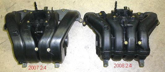
Look at the picture below for the difference between the 06-07 and 08 style manifolds


Thread
Thread Starter
Forum
Replies
Last Post