
Dual Pass intercooler

Thread Starter
Senior Member
Joined: 04-03-06
Posts: 7,570
Likes: 0
From: Mesa, AZ
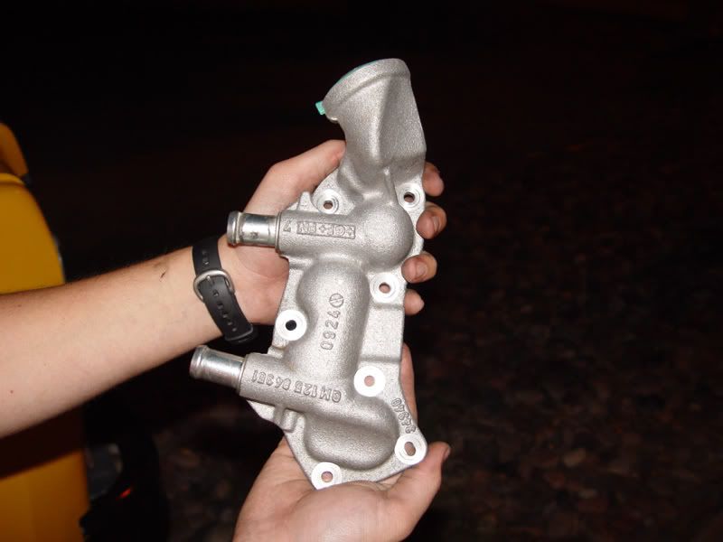
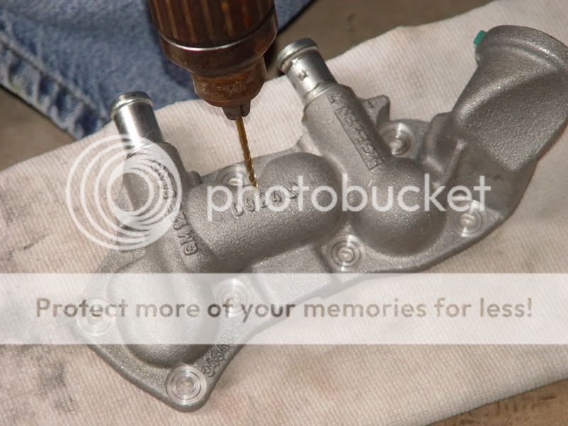
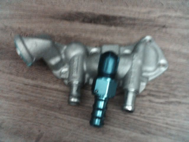
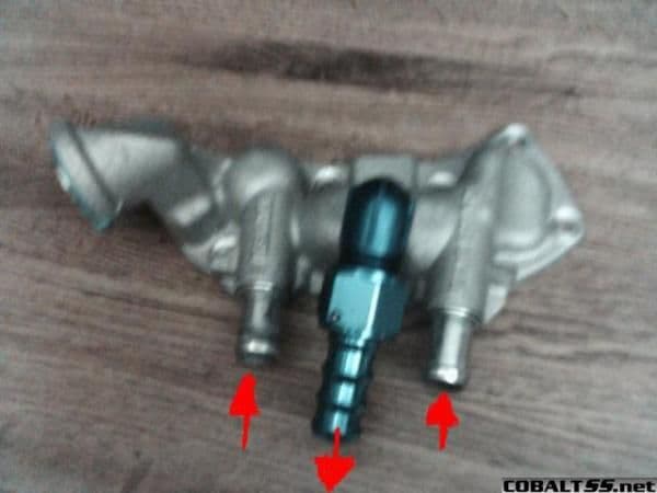
The parts I used was a 1/2 NPT fitting with a 3/4" hose barb (hard to find). The hole was 1/2 inch, we tapped it, but couldn't get it to seal so we just had it welded. The middle fitting goes up to the filler tube. Oh you also need a T or Y fitting with a 3/4" hose barb on all sides.
Senior Member
Joined: 07-08-05
Posts: 6,200
Likes: 0
From: Niceville, FL
Originally Posted by Blown 4-banger
The parts I used was a 1/2 NPT fitting with a 3/4" hose barb (hard to find). The hole was 1/2 inch, we tapped it, but couldn't get it to seal so we just had it welded. The middle fitting goes up to the filler tube. Oh you also need a T or Y fitting with a 3/4" hose barb on all sides.
Could you post pics on the ss.net gallery for me to see? I can see pics from other sites and I'm really interested in this. All I have to do is drill a hole, add a 3/4" hose barb, and reinstall to have a dual pass setup? If that's it, I'm doing this when I get home! Thanks for the info!


Senior Member
Joined: 10-08-05
Posts: 5,295
Likes: 0
From: AZ
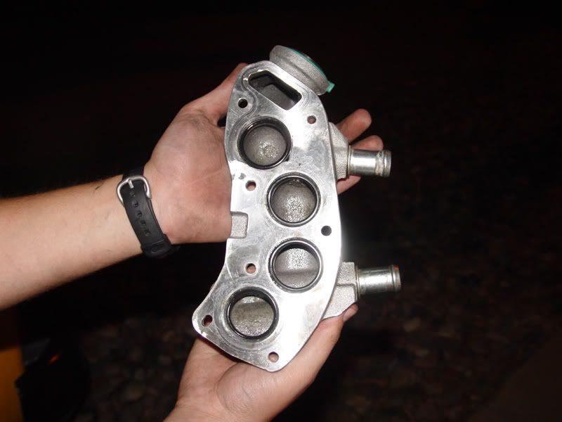
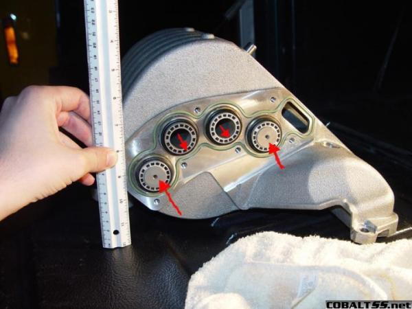
Besure to take the intake manifold off and switch the top 2 cores like in the image above. They are directional.
It should be but if not JBP has a higher flowing pump, not sure if they will sell it without the rest of their "4 pass" IC setup.
Originally Posted by M88ArRamadi
Good Thread!!
I was going to do all 3 (CA Heat Exchanger, Dual Pass, Meth inj.) But I was going to start with Meth.
Will the IC pump be enough for the dual pass?
I was going to do all 3 (CA Heat Exchanger, Dual Pass, Meth inj.) But I was going to start with Meth.
Will the IC pump be enough for the dual pass?
Senior Member
Joined: 10-08-05
Posts: 5,295
Likes: 0
From: AZ
Pull the cores out and flip them around, Blown 4-banger should still have the before and after pics he just has to upload them.
The JBP "4 pass" is really a dual pass with supposedly "custom laminova cores" and fancy stainless steel braided lines. You have to root through all the junk to get the real info. Post#86 is the most usefull IMO. https://www.cobaltss.net/forums/show...t=35670&page=5
The JBP "4 pass" is really a dual pass with supposedly "custom laminova cores" and fancy stainless steel braided lines. You have to root through all the junk to get the real info. Post#86 is the most usefull IMO. https://www.cobaltss.net/forums/show...t=35670&page=5
Senior Member
Joined: 10-08-05
Posts: 5,295
Likes: 0
From: AZ
Originally Posted by 2K5SS/SC?
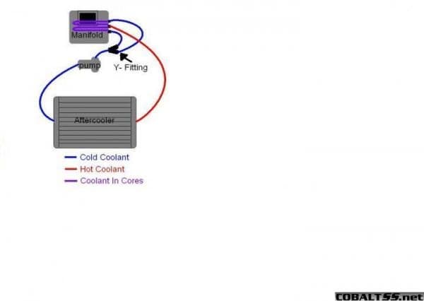
I'll take this project over the headgasket replacement I did any day!  Plus, it'll benefit my car greatly being in Charleston 100+ degree weather in the summer time. Can someone make a flow diagram (with paint or something as it doesn't have to be too detailed) and post it? I think that would help us all out getting a idea of how it works.
Thread Starter
Senior Member
Joined: 04-03-06
Posts: 7,570
Likes: 0
From: Mesa, AZ
Originally Posted by 2K5SS/SC?
Is this an accurate picture of the overall idea here? I thought this visual might help out even more if it is indeed correct.
Originally Posted by Zinner
This is sticky worth. Great info.


New Member
Joined: 07-25-06
Posts: 196
Likes: 0
From: Connecticut
Your instructions are great, I just recieved the GM kit but it says to run the flow opposite to your instructions.
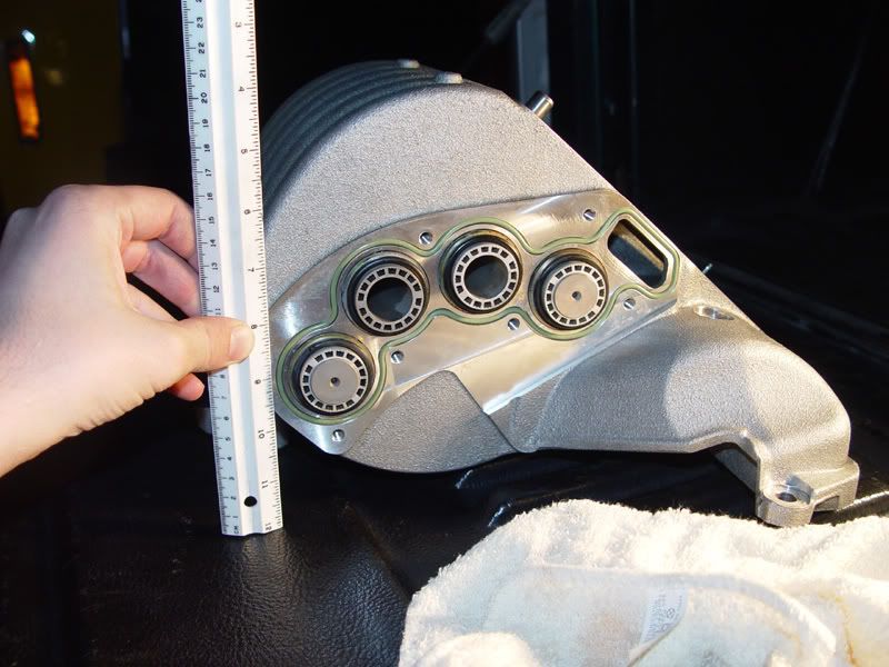
GM says install the small orifice tubes in the 2 middle holes and the large ones top and bottom, they also are runing the water in the oposite direction, the center port is IN and the top and bottom Ports are OUTS.
The also talk about adding a second surge tank to better purge the air from the system and add capacity using a Saturn Red Line Surge tank, another T and a 0.040 bleed orifice to the other end of the intercooler.
Would you care to elaborate?
Senior Member
Joined: 07-08-05
Posts: 6,200
Likes: 0
From: Niceville, FL
I suppose you could do it that way too. I think it might actually keep the coolant cooler that way too because it would separate the heated cores even further until it exits the manifold. Mmmm..... Interesting. Someone needs to do a test to see which one is better.

Senior Member
Joined: 10-08-05
Posts: 5,295
Likes: 0
From: AZ
Originally Posted by JANNETTYRACING
Your instructions are great, I just recieved the GM kit but it says to run the flow opposite to your instructions.
GM says install the small orifice tubes in the 2 middle holes and the large ones top and bottom, they also are runing the water in the oposite direction, the center port is IN and the top and bottom Ports are OUTS.
The also talk about adding a second surge tank to better purge the air from the system and add capacity using a Saturn Red Line Surge tank, another T and a 0.040 bleed orifice to the other end of the intercooler.
http://www.crateenginedepot.com/stor...P1693C196.aspx

The extra surge tank and bleed orfice would have made things a world easier. Blown 4-banger spent several hours slowly purged the air by repeatedly starting the IC pump, stoping the pump and adding fluid as needed. I would recommend doing this while you install a new or additional HE just to prevent having to bleed the system twice.


Member
Joined: 11-01-06
Posts: 324
Likes: 0
From: Port St Lucie
Originally Posted by Blown 4-banger
The parts I used was a 1/2 NPT fitting with a 3/4" hose barb (hard to find). The hole was 1/2 inch, we tapped it, but couldn't get it to seal so we just had it welded. The middle fitting goes up to the filler tube. Oh you also need a T or Y fitting with a 3/4" hose barb on all sides.