2.0 LSJ Engine: How to Log AFR Using A/C Pressure (Big Pictures)
 03-30-2012, 04:35 PM
#1
Junior Member
Thread Starter

Join Date: 09-05-10
Location: South Carolina
Posts: 427
Likes: 0
Received 0 Likes
on
0 Posts
How to Log AFR Using A/C Pressure (Big Pictures)
The A/C Pressure sensor outputs a 0-5v signal to the PCM. The PCM uses this signal to control things like designated fan speed for the sensed A/C pressure. Most, if not all widebands also have a wire that outputs a 0-5v signal proportional to your AFR. This makes it convenient to use the A/C Pressure pin on the PCM to sense AFR and log it in HPTuners. Now, I know what your asking, "How is logging a 0-5v signal going to tell me what my AFR is?" In HPTuners you can create custom PID's by using functions. So it becomes a simple math problem when converting from a 0-5v signal to an actual AFR that you can use.
First things first, gather your tools...
Wire Strippers
Butt Connectors
Female Lugs
Plenty of Wire
5 pin relay
SPST Rocker Switch (or any other type of toggle switch)
Wiring Diagram for A/C System (if desired)

METHOD
Before doing any electrical work, you should isolate the battery to deenergize most if not all of the car's electrical systems.
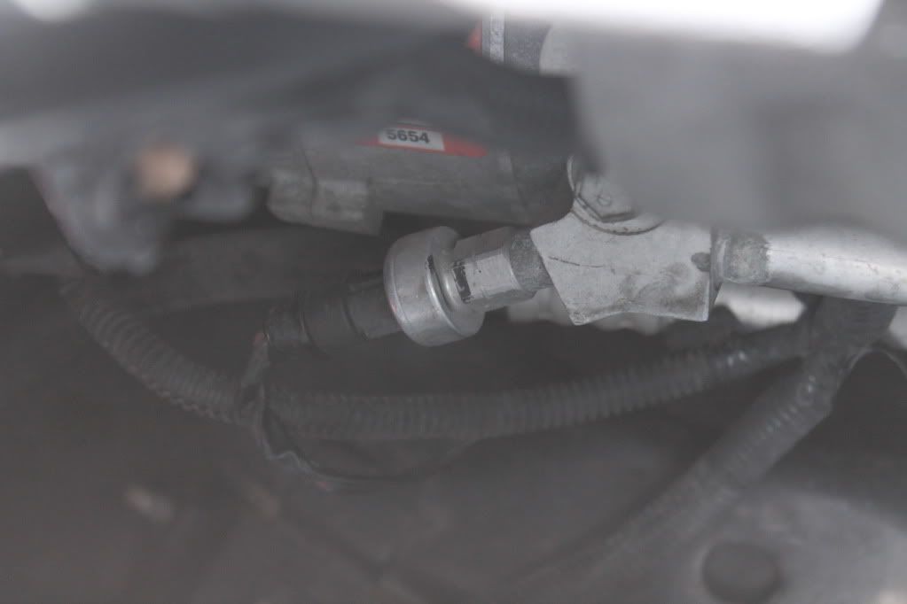
Locate your A/C Pressure sensor. If you look down between the intake manifold and the radiator fans on the passenger side of the car, you will see A/C piping and a small sensor sticking out the side. Coming off the sensor there should be a grey, black, and red+black wire coming out of it. The red+black wire is what you're after.

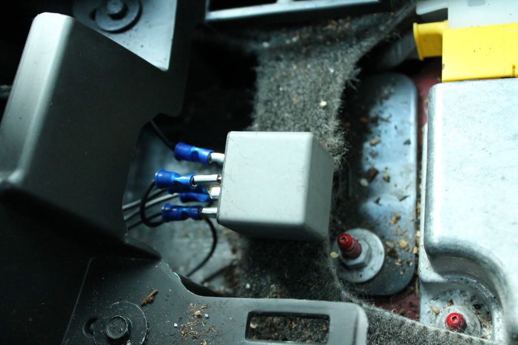
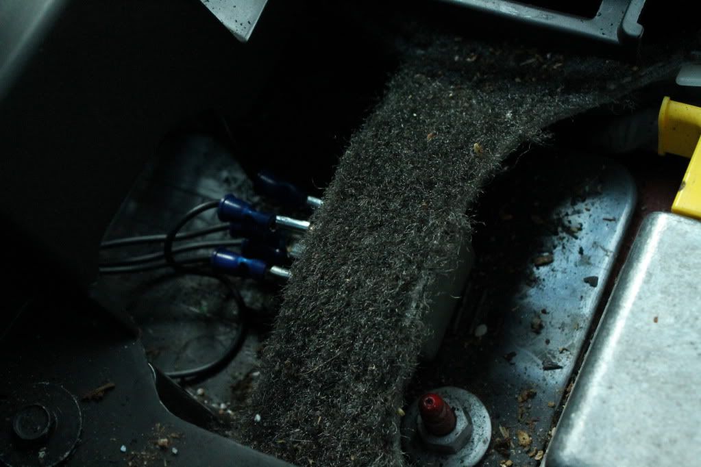
Find a location suitable for the 5 pin relay. Keep in mind that allowing any of the pins to touch metal will cause a ground and could blow a fuse or short out vital systems. Use the male lugs as connectors for the pins and connect them to the appropriate locations. I removed the panels covering the shifter and the E-brake and put the relay in front of the E-brake.
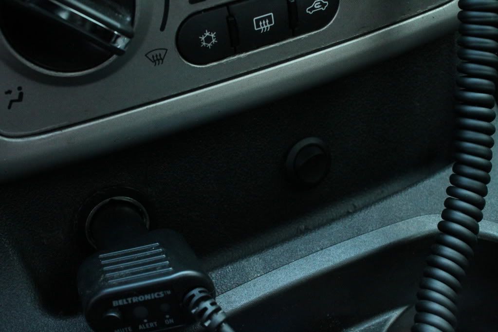
Now find a suitable location for the rocker switch. This switch will determine whether the relay has power, and ultimately whether your PCM is receiving a signal from the wideband or from the actual A/C pressure sensor.
The rest of the install is simple wiring.I recommend using the already installed grommit in the firewall behind the pedals. Fishing wire through that hole and up through your engine bay can be a pain, but it beats having to drill new holes and install new grommits.
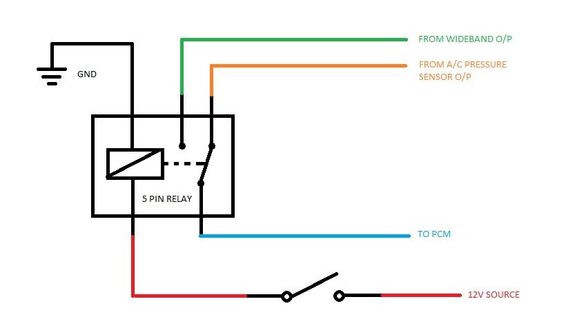
The pin normally aligned with the PCM pin needs to be the signal from the A/C Pressure Sensor. This ensures that when the relay is deenergized, the PCM is actually seeing A/C System pressure, but when you want to log, you hit the toggle switch, energizing the relay and switching the feeder signal from the Pressure sensor to the wideband.
Your PCM will still think its reading A/C Pressure, but its actually seeing the output from the wideband. As long as your .cfg file in HPT has the proper correction factor you should be logging AFR at this point. To check and see if the relay is working properly, or ensure the wires are connected to the right pins, simply log A/C Pressure (volts) in HPT and you should see a pretty big difference between when the toggle switch is shut vs. open.
CAUTION: While wiring through your engine bay, keep in mind that extreme heat and plastic don't mix. Letting wires drape on top of the engine or near exhaust piping can cause the insulation to melt and expose bare wire. This raises your chance for an inadvertant ground and damage to your cars electrical system.
Creating Your Custom PID
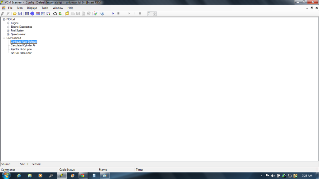
At the screen to select the new PID, go to "Configure User Defined"
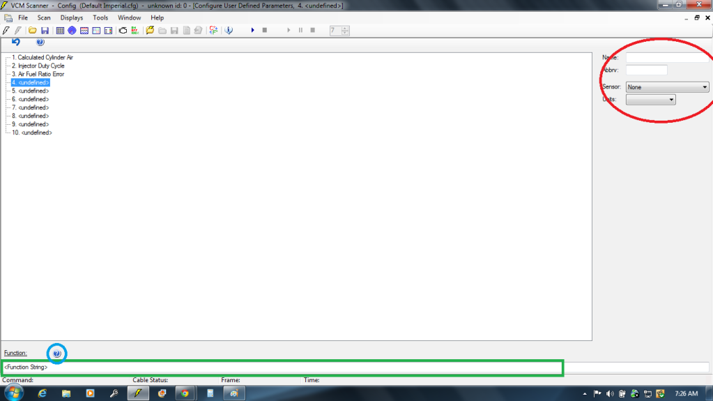
First the easy part. Name the new PID using the boxes on the right (red). Now the hard part. You have to develop a function to convert the voltage sensed at the AC Pressure signal to the corresponding AFR. To do this you're going to have to do some linear algebra. Once you solve for the function, type the function into the "Function String" box (Green). In order for this to work, you have to use existing PID's as variables. But don't worry, you don't just have to know the PID numbers off the top of your head. If you click the question mark (blue) it will bring up a list of PID's and Sensors supported on your vehicle (or loaded by your config file)
Solving for your correction function.
This part is kind of arduous. Make sure you've added AC Pressure (Volts) to the table. You're going to log idle AFR's in closed loop to gather data points. The way to do this is set up a chart to display the fluctuating AC Press voltage. Start the car and start the log. While the car is running, you should be seeing a slight fluctuation in AFR. Keep your hand ready to hit the space bar (hitting space bar will stop/start the log). Watch your wideband and wait for it to momentarily hang on a number. When it does, immediately hit space bar. The goal is to record the exact voltage that corresponds to the AFR you saw. Write this voltage and AFR pair down somewhere! you will need it later.
Repeat this process one more time to get a different data point.
Once you have two data points, you can use linear algebra to determine the exact equation needed to compensate for the wideband signal. (HINT: The larger the difference between points the better)
Example:
@ 11.3 AFR, wideband output was 1.06V
@ 13.9 AFR, wideband output was 2.24V
Therefore the wideband outputs a signal along the line running through (1.06,11.3) and (2.24,13.9)
Using the equation y=mx+b we can solve for everything we need.
Where: y = AFR Reading
m = Wideband scalar
x = Output voltage
b = Wideband offset
So right now, we know x and y. To find m use the equation: (Y2-Y1)/(X2-X1)
Where: Y1 and Y2 = AFR values
X1 and X2 = Output voltages
Example: (13.9-11.3)/(2.24-1.06) = 2.203389830508475
This is our Wideband scalar
If we plug all these variables back in, we can easily solve for the Wideband offset.
y=mx+b--->y=b+mx--->y-mx=b--->(AFR value)-(Wideband scalar*Output Voltage) = Wideband Offset
Example: (13.9)-(2.203389830508475*2.24) = 8.964406779661016
This is our Wideband offset.
Now we have everything we need to write a function string for our new PID.
AC Pressure Volts PID = [PID.7101]
Commanded AFR PID = [SENS.121]
[PID.7101] * 2.203389830508475 + 8.964406779661016
THESE PID NUMBERS CAME FROM A 2006 LSJ. THEY MAY BE DIFFERENT FOR OTHER MODEL YEARS
Your function string should end up being the same as your line equation:
(AC Pressure Volts) * (Wideband Scalar) + (Wideband Offset)
To create a PID for AFR Error, you need to slightly modify the function:
((((AC Pressure Volts) * (Wideband Scalar) + (Wideband Offset)) - (Commanded AFR)) * 100) / (Commanded AFR)
Once you have your custom PID setup, you can use custom histograms to record AFR error with regards to Primary VE vs. RPM vs. MAP or MAF frequency.
First things first, gather your tools...
Wire Strippers
Butt Connectors
Female Lugs
Plenty of Wire
5 pin relay
SPST Rocker Switch (or any other type of toggle switch)
Wiring Diagram for A/C System (if desired)
METHOD
Before doing any electrical work, you should isolate the battery to deenergize most if not all of the car's electrical systems.
Locate your A/C Pressure sensor. If you look down between the intake manifold and the radiator fans on the passenger side of the car, you will see A/C piping and a small sensor sticking out the side. Coming off the sensor there should be a grey, black, and red+black wire coming out of it. The red+black wire is what you're after.
Find a location suitable for the 5 pin relay. Keep in mind that allowing any of the pins to touch metal will cause a ground and could blow a fuse or short out vital systems. Use the male lugs as connectors for the pins and connect them to the appropriate locations. I removed the panels covering the shifter and the E-brake and put the relay in front of the E-brake.
Now find a suitable location for the rocker switch. This switch will determine whether the relay has power, and ultimately whether your PCM is receiving a signal from the wideband or from the actual A/C pressure sensor.
The rest of the install is simple wiring.I recommend using the already installed grommit in the firewall behind the pedals. Fishing wire through that hole and up through your engine bay can be a pain, but it beats having to drill new holes and install new grommits.
The pin normally aligned with the PCM pin needs to be the signal from the A/C Pressure Sensor. This ensures that when the relay is deenergized, the PCM is actually seeing A/C System pressure, but when you want to log, you hit the toggle switch, energizing the relay and switching the feeder signal from the Pressure sensor to the wideband.
Your PCM will still think its reading A/C Pressure, but its actually seeing the output from the wideband. As long as your .cfg file in HPT has the proper correction factor you should be logging AFR at this point. To check and see if the relay is working properly, or ensure the wires are connected to the right pins, simply log A/C Pressure (volts) in HPT and you should see a pretty big difference between when the toggle switch is shut vs. open.
CAUTION: While wiring through your engine bay, keep in mind that extreme heat and plastic don't mix. Letting wires drape on top of the engine or near exhaust piping can cause the insulation to melt and expose bare wire. This raises your chance for an inadvertant ground and damage to your cars electrical system.
Creating Your Custom PID
At the screen to select the new PID, go to "Configure User Defined"
First the easy part. Name the new PID using the boxes on the right (red). Now the hard part. You have to develop a function to convert the voltage sensed at the AC Pressure signal to the corresponding AFR. To do this you're going to have to do some linear algebra. Once you solve for the function, type the function into the "Function String" box (Green). In order for this to work, you have to use existing PID's as variables. But don't worry, you don't just have to know the PID numbers off the top of your head. If you click the question mark (blue) it will bring up a list of PID's and Sensors supported on your vehicle (or loaded by your config file)
Solving for your correction function.
This part is kind of arduous. Make sure you've added AC Pressure (Volts) to the table. You're going to log idle AFR's in closed loop to gather data points. The way to do this is set up a chart to display the fluctuating AC Press voltage. Start the car and start the log. While the car is running, you should be seeing a slight fluctuation in AFR. Keep your hand ready to hit the space bar (hitting space bar will stop/start the log). Watch your wideband and wait for it to momentarily hang on a number. When it does, immediately hit space bar. The goal is to record the exact voltage that corresponds to the AFR you saw. Write this voltage and AFR pair down somewhere! you will need it later.
Repeat this process one more time to get a different data point.
Once you have two data points, you can use linear algebra to determine the exact equation needed to compensate for the wideband signal. (HINT: The larger the difference between points the better)
Example:
@ 11.3 AFR, wideband output was 1.06V
@ 13.9 AFR, wideband output was 2.24V
Therefore the wideband outputs a signal along the line running through (1.06,11.3) and (2.24,13.9)
Using the equation y=mx+b we can solve for everything we need.
Where: y = AFR Reading
m = Wideband scalar
x = Output voltage
b = Wideband offset
So right now, we know x and y. To find m use the equation: (Y2-Y1)/(X2-X1)
Where: Y1 and Y2 = AFR values
X1 and X2 = Output voltages
Example: (13.9-11.3)/(2.24-1.06) = 2.203389830508475
This is our Wideband scalar
If we plug all these variables back in, we can easily solve for the Wideband offset.
y=mx+b--->y=b+mx--->y-mx=b--->(AFR value)-(Wideband scalar*Output Voltage) = Wideband Offset
Example: (13.9)-(2.203389830508475*2.24) = 8.964406779661016
This is our Wideband offset.
Now we have everything we need to write a function string for our new PID.
AC Pressure Volts PID = [PID.7101]
Commanded AFR PID = [SENS.121]
[PID.7101] * 2.203389830508475 + 8.964406779661016
THESE PID NUMBERS CAME FROM A 2006 LSJ. THEY MAY BE DIFFERENT FOR OTHER MODEL YEARS
Your function string should end up being the same as your line equation:
(AC Pressure Volts) * (Wideband Scalar) + (Wideband Offset)
To create a PID for AFR Error, you need to slightly modify the function:
((((AC Pressure Volts) * (Wideband Scalar) + (Wideband Offset)) - (Commanded AFR)) * 100) / (Commanded AFR)
Once you have your custom PID setup, you can use custom histograms to record AFR error with regards to Primary VE vs. RPM vs. MAP or MAF frequency.
Last edited by Jdam8139; 06-12-2012 at 05:59 PM. Reason: Added method for creating new PID
 08-07-2012, 06:39 PM
#4
Junior Member
Thread Starter
Join Date: 09-05-10
Location: South Carolina
Posts: 427
Likes: 0
Received 0 Likes
on
0 Posts
Yeah, I wanted to be able to log AFR instead of using trims, but didn't have HPT Pro. So I used one of the corvette sites and adapted it to my car. Took a leap of faith, and ended up cutting the wrong wire the first time lol real close call


 05-26-2013, 12:30 AM
#13
Platinum Member
Platinum Member
Relays work great and all but it's really overkill for something like this. Just use a single pole double throw switch and call it a day. Far easier, fewer wires to run and just as much if not more reliable than a relay setup. Just my .02
05-29-2013, 03:37 PM
#14
I dropped the whole 5 pin relay, it's too complicated. No actual wire diagrams that show how to do this. Just show 5 pin relay wire diagrams that it. Need to have more Infos of where all those wires hook up to give better Infos about wire diagrams. So I hook up my (AEM) Wideband red wire with fuse tap on the passenger side fuse box where there wiper fuse is, black (ground) hook on any metal that has bolt. Then use white wire from (AEM) Wideband to hook on the top of rocker switch then PCM go to the middle, A/C pressure sensor go to the bottom of rocker switch. It works like a charm.
06-01-2013, 06:35 PM
#16
Platinum Member
Platinum Member
I'm glad you were able to make the single pole double throw setup work. That's all I've ever ran and it's never failed me. Don't get me wrong though, doing this with a relay is definitely not a bad idea in the least, but it's a little more than it needs to be for something like this imo.
06-01-2013, 06:55 PM
#17
Yeah, It's very simple and less wires also. I can say it's a good thing, as for 5 pin relay may be cool but more wires and headaches! I had fought for 1 1/2 weeks trying to get this work but didn't. Cause OP didn't show the whole wire diagrams to show how you can really do this. OP just show 5 pin relay that's it but what about rocker switch n wideband go to where ? Let's hope OP will make specific details of how to do this. If He gets around here on this forums.
06-21-2013, 11:45 AM
#18
Junior Member
Thread Starter
Join Date: 09-05-10
Location: South Carolina
Posts: 427
Likes: 0
Received 0 Likes
on
0 Posts
Sorry guys, I just recently got back from being underway. I'm in the Navy assigned to a submarine out of Groton, CT and, well, being hundreds of feet underwater isn't exactly conducive to keeping up with emails and stuff.
I can't believe I didn't think of the SPDT switch . I guess I just used what I'm used to being around. We have tons of relays controlling everything on the boat, so that's what I was familiar with. Now that I think about it though, we have tons of SPDT switches too... oh well haha. I'm glad it worked though, it's definitely an improvement.
As for the 5 pin relay, for anyone who may still want to go that route. The rocker switch I used only supplies/interrupts power to the relay. A relay works using an electromagnet to move a switch. You turn the magnet on, the switch shuts, and vice versa. So you just put the rocker switch inline with the power going to the coil in the relay, and voila. Depending on the rocker switch, however, it might have an LED to indicate when it's on. For this, you wire it up with one wire coming from the power supply into the switch, another wire going from the switch to the relay, and the third going from the switch to ground. That will allow the LED to come on when the switch is shut.
I hope that helps. I didn't think the wiring needed much more than I provided. My drawing shows the switch inline with the relay's power supply, just like I described. Maybe I'm confusing where it is you got confused haha.
I can't believe I didn't think of the SPDT switch . I guess I just used what I'm used to being around. We have tons of relays controlling everything on the boat, so that's what I was familiar with. Now that I think about it though, we have tons of SPDT switches too...
oh well haha. I'm glad it worked though, it's definitely an improvement.As for the 5 pin relay, for anyone who may still want to go that route. The rocker switch I used only supplies/interrupts power to the relay. A relay works using an electromagnet to move a switch. You turn the magnet on, the switch shuts, and vice versa. So you just put the rocker switch inline with the power going to the coil in the relay, and voila. Depending on the rocker switch, however, it might have an LED to indicate when it's on. For this, you wire it up with one wire coming from the power supply into the switch, another wire going from the switch to the relay, and the third going from the switch to ground. That will allow the LED to come on when the switch is shut.
I hope that helps. I didn't think the wiring needed much more than I provided. My drawing shows the switch inline with the relay's power supply, just like I described. Maybe I'm confusing where it is you got confused haha.
09-20-2018, 11:02 PM
#19

bringing to life an old thread, but I got an idea where u don't have to do a thing with a switch, everything is automatic. why not use a relay, which will get its power from a quick circuit connected at the ac clutch fuse, which if im reading the wire diagram correctly only is energized when ac is turned on. so using the relay to switch between the o2 and ac pressure switch signals, the o2 would always be active until ac is turned on, then the relay would energize and switch to ac pressure switch signal. little more complicated that a toggle switch, but still easy, and don't have to wire into the cabin at all.
 Moderator
Thread
Thread Starter
Forum
Replies
Last Post
flash13brandon
2.0L LSJ Performance Tech
8
05-15-2009 10:03 PM