
Intake manifold


Junior Member
Joined: 03-06-08
Posts: 409
Likes: 0
From: Ledyard, CT
I think arguing over a forum is lame so I and I am not going to get pulled in.
Sorry but when people start swearing in a reply i didn't think it was neccessary to reply but I do have some facts to add to the value of this thread.
STS2/SS first said the ports were 5cm tall. The Laminova core is not even 4cm tall. Its 39.5mm actually. Then he said the the port was 5 inches long. Close but it closer to 7 inches.
Sorry but I got a kick out of STS2's attitude toward Omega. Omega has been working on improving the LSJ manifold for a long time and STS2 didn't have a clue what he was talking about.
If you are going to throw out numbers as facts make sure they are right.
Beerman, do you have anything to add to this thread other then...
and
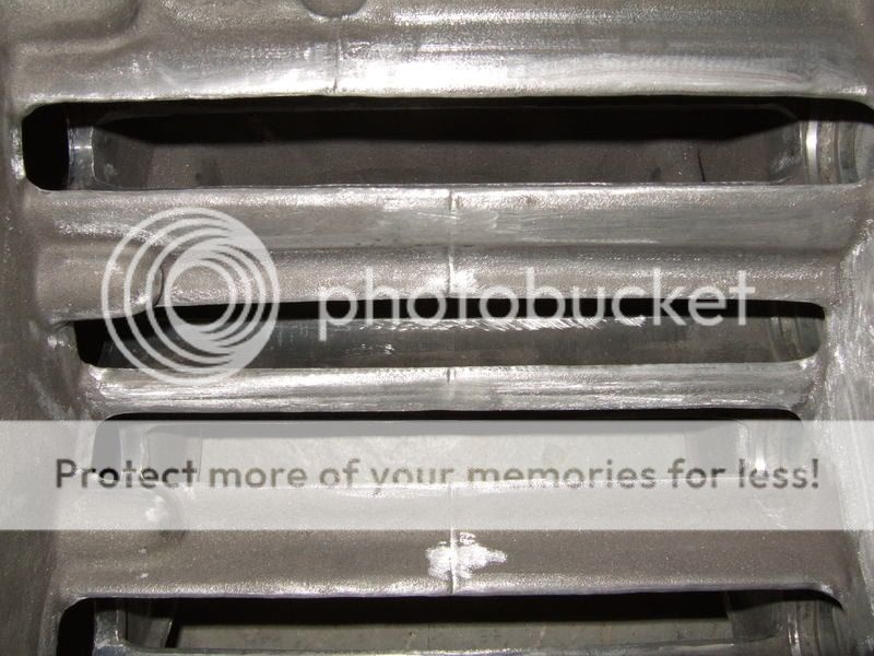
Here is the inside of an LSJ intake manifold since you have never seen one.
Back side stock.

Back side ported.
Front side ported.

Top side ported.
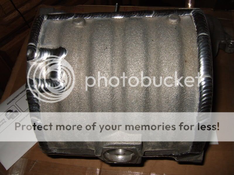
Welds
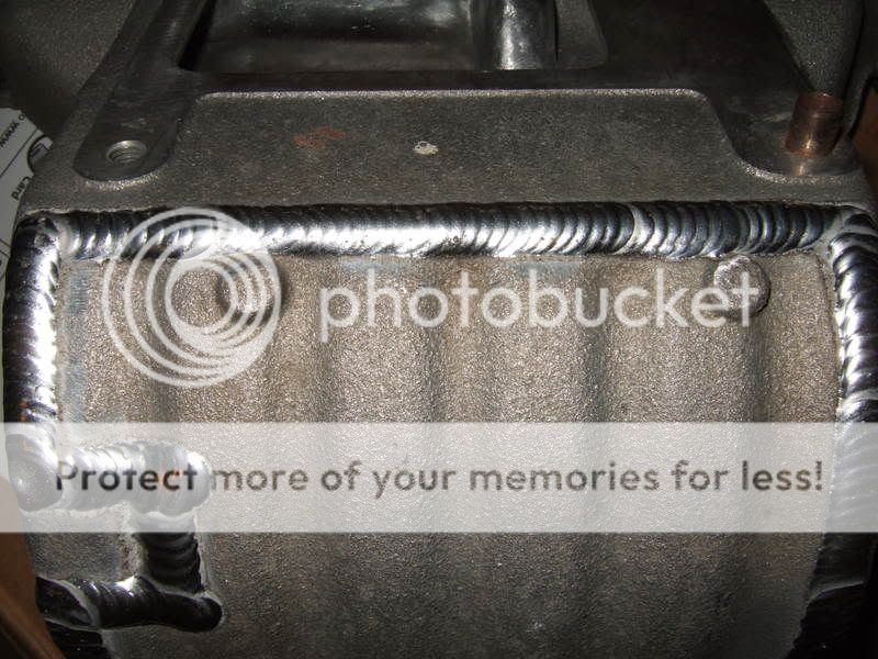
Those are pics of the ported IM that is sitting in my garage right now. Is there anything else I can help answer for you?
Sorry but when people start swearing in a reply i didn't think it was neccessary to reply but I do have some facts to add to the value of this thread.
STS2/SS first said the ports were 5cm tall. The Laminova core is not even 4cm tall. Its 39.5mm actually. Then he said the the port was 5 inches long. Close but it closer to 7 inches.
Sorry but I got a kick out of STS2's attitude toward Omega. Omega has been working on improving the LSJ manifold for a long time and STS2 didn't have a clue what he was talking about.
If you are going to throw out numbers as facts make sure they are right.
Beerman, do you have anything to add to this thread other then...
and
Here is the inside of an LSJ intake manifold since you have never seen one.
Back side stock.
Back side ported.
Front side ported.
Top side ported.
Welds
Those are pics of the ported IM that is sitting in my garage right now. Is there anything else I can help answer for you?
True on the measurements, I stand corrected. My point still stands, the manifold sucks!!!
I'm going friday and saturday to the shop to weld the manifold it should take awhile I'll send pics. Also I've figured out away to make it less steep. Thanks for the input.
It would be nice to be able to flip the SC over and do a front mount setup. Some one should do it! I know I'm not the only one with the testicular fortatude to attempt engineering feets like the one I'm attemting now.
Last edited by STS2/SS; Sep 18, 2008 at 07:40 AM. Reason: Automerged Doublepost

Senior Member
Joined: 02-05-06
Posts: 727
Likes: 0
From: Kakabeka Falls, Ontario
THere is a design in the works for a front mount. You would not need to flip the SC over. If you have a front mount, you do not need to have cooling inegrated with the Manifold. THis way you have the room for proper plenum and runners.

Haz l33t wheelz.

Joined: 09-14-07
Posts: 18,883
Likes: 3
From: Costa Mesa CA
**** man! share some more info!!!!!!!

Senior Member
Joined: 02-05-06
Posts: 727
Likes: 0
From: Kakabeka Falls, Ontario
*I* dont have a design - I have an electrical engineering background and I live in the country - I dont have access to the software or the hardware to begin to attempt this.
I can only offer a description:
- Manifold has 2 chambers that are stacked ontop of each other but are completely separate - each chamber has a side exit fitting so you can hook up a charge tube to it.
- The upper chamber is connected to the SC outlet and provides a bit of volume before the air exits this first chamber (out the side exit) and through a charge tube that leads to the FMIC inlet.
- The FMIC outlet will run into the bottom chamber, which is larger and has runners running from it to the head.
It should take up roughly the same space as the existing IM - but with no space neesed for the laminovas, endplate, and water piping, you could fit a proper plemun and runners in there.
*I* have nothing to show.
I cant take credit - the idea was bouncing around in other people's heads before I mentioned it. Once things are done, I am sure that person will post it up.
Senior Member
Joined: 10-01-06
Posts: 5,134
Likes: 0
From: Maidstone, SK

Junior Member
Joined: 03-06-08
Posts: 409
Likes: 0
From: Ledyard, CT
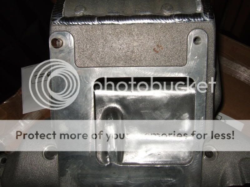
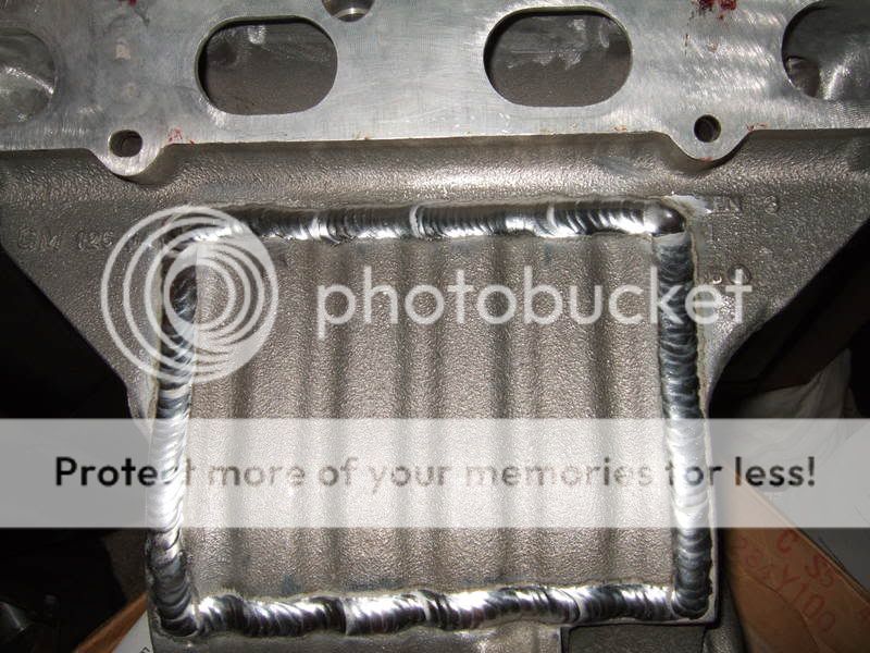
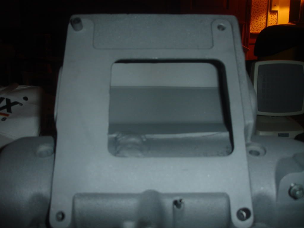
Check it I have the divider installed. I just finished sandblasting and tomarow I will finish welding so don't mind all of the gaps they will be filled!
Now instead of blowing directly onto a plate for some odd reason? I've cutout that plate and welded in a divider that I made 2, 30 degree bendes and tacked in place.
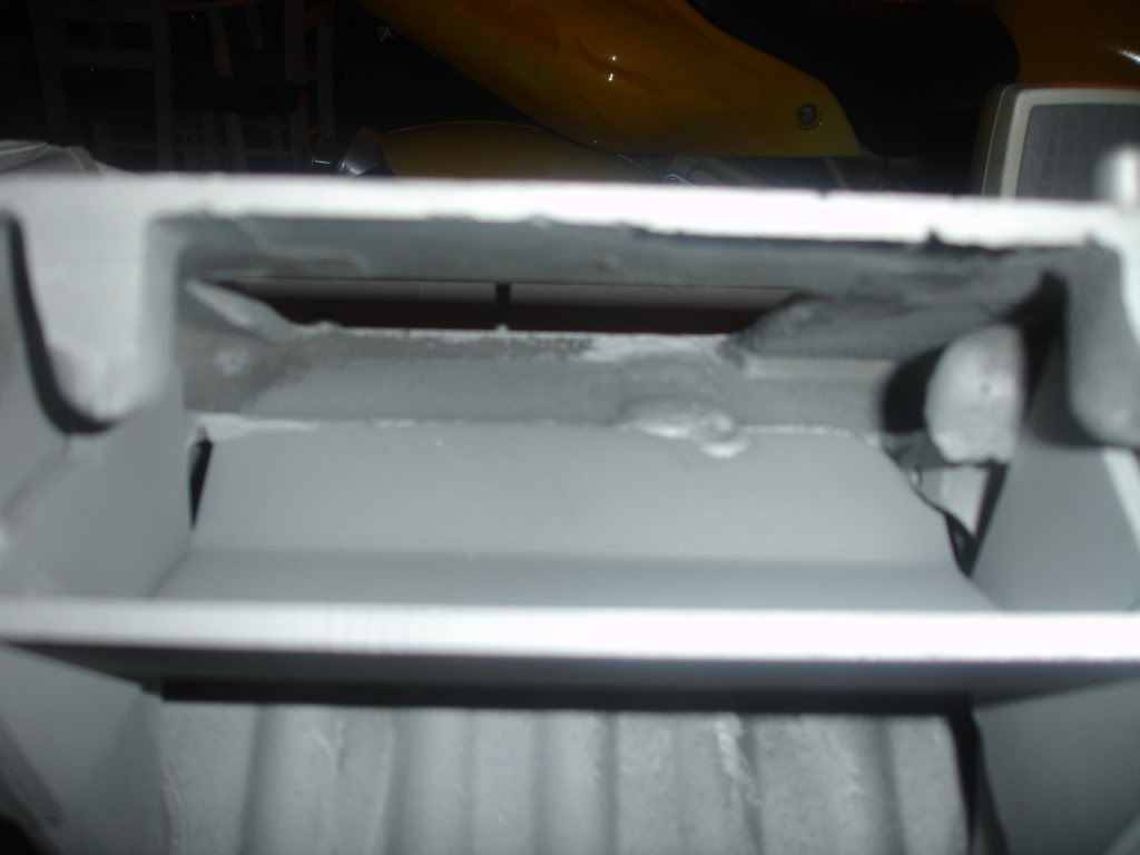
Here is a top view of the new divider!
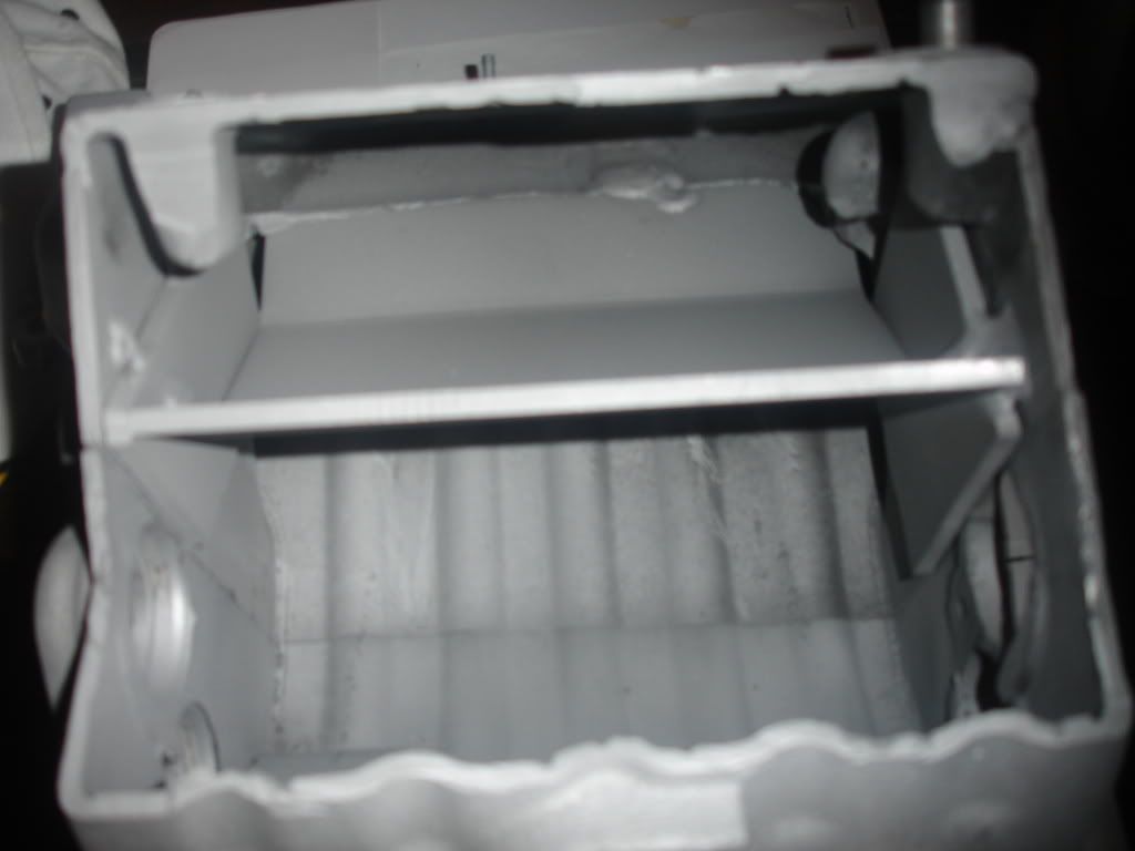
Here is a front view of how I seperated the top from the bottom to seperate the supercharger output from the inlet to the engine!
Now the intercooler core will weld right to the front like so ish.......
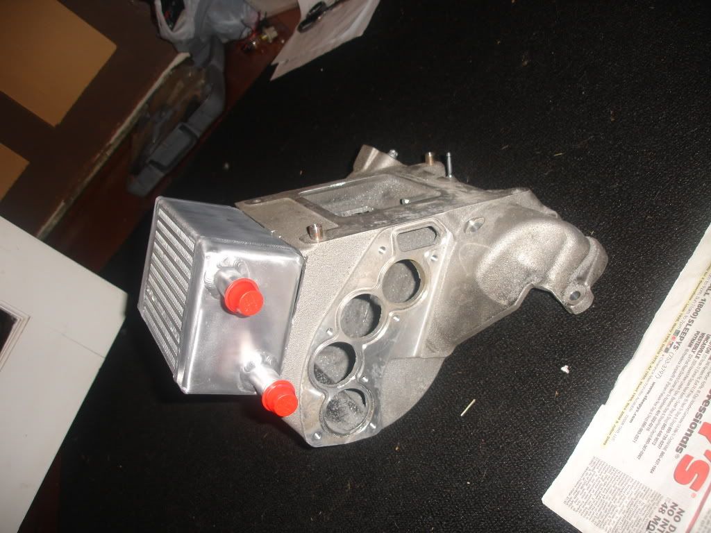
More pictures to come!
Now instead of blowing directly onto a plate for some odd reason? I've cutout that plate and welded in a divider that I made 2, 30 degree bendes and tacked in place.
Here is a top view of the new divider!
Here is a front view of how I seperated the top from the bottom to seperate the supercharger output from the inlet to the engine!
Now the intercooler core will weld right to the front like so ish.......
More pictures to come!

Senior Member
Joined: 09-21-06
Posts: 2,270
Likes: 1
From: Midwest
I've been working on my own design for an intake manifold and an oil cooler. I don't need them cleaned, I'll be doing that anyway, but yeah, I'd like the o-rings, etc as well. I assume you have a set of four? What's sounds fair to you?
he will take the original curved end piece add an extention to it and cap it off that way. the air will go through the top half turn around and go through the bottom half back to the engine
Junior Member
Joined: 03-06-08
Posts: 409
Likes: 0
From: Ledyard, CT
how about $150, this includes shipping!
Haz l33t wheelz.
Joined: 09-14-07
Posts: 18,883
Likes: 3
From: Costa Mesa CA
i'll have to see it finished, i'm making a drawing, forgive the crudeness, paint is all i have. i would do CAD, but i don't have the program in Iraq.

the gray block is the stock intake manifold with the guts/laminova's removed.
red is your director plate that was just welded in.
the "clear" box is the mini intercooler
the rounded thing is the curve of the stocker welded back on.
green is the intercooler core
blue is the airflow. now, if i'm not mistaken, that's what you're talking about doing right?
now whats going to keep that air that turned abound from going back the way it came, other than boost pressure?
i could be wrong, please prove me so.
there has to be a plate inside the intercooler itself, then a flow director in the rounded section.
Last edited by ls1fbody; Sep 25, 2008 at 02:45 PM. Reason: Automerged Doublepost
Air follows the path of least resistance... It would be "pushed" into the intake manifold from the positivite displacement M62, building boost, and then it would be "sucked" into the cylinder head by the vacuum action of the intake stroke of the engine... I hate physics, but that is my undertanding?
The only thing I see is that the air might not pass over the intercooler fins enough for it to fully cool since it has to take such a convoluted path...
Overall this looks very promising... I would be extremely interested in a setup like this or even a ported intake manifold. If someone for the love of God could just finally prove the gains of a revised intake manifold!
Haz l33t wheelz.
Joined: 09-14-07
Posts: 18,883
Likes: 3
From: Costa Mesa CA
i agree, it would eventually follow that path, but it just seems like a very inefficient way to go about it. the air would just collect in that pocket, and then make it's way through the intercooler. i hope it works out because we need something.
I agree! I would really like to see something new come out of this...
It would be really nice if someone could make a nice intake manifold that went basically straight down flow through an intercooler mounted right below the blower straight into the head... Kinda like the 3800 motors intake that ZZP sells for the M90...
It would be really nice if someone could make a nice intake manifold that went basically straight down flow through an intercooler mounted right below the blower straight into the head... Kinda like the 3800 motors intake that ZZP sells for the M90...
^^if that picture is correct that doesnt seem logical...
Air taking a hard 90, then a complete 180? Poor air flow design... If it takes that path, the intercooler will not be as effective because the air will turn and travel on the outter portion of the intercooler...
I guess I dont get it either... I guess posting up what you are actually gunna do.
Air taking a hard 90, then a complete 180? Poor air flow design... If it takes that path, the intercooler will not be as effective because the air will turn and travel on the outter portion of the intercooler...
I guess I dont get it either... I guess posting up what you are actually gunna do.
ya thats about it... the path it follows is the metal hes welded into the gutted intercooler, its got two 30 degree bends in it. yes the intercooler is split into two halfs. and we arent just placing the end piece back on, there will be a small spacer in there to give the air a bit more room.
its an amazingly efficient intercooler. and for anyone who is complaining about how bad the curve will be for the air, honestly have you ever looked at the original piece and how it works with the laminovas? it will make way more power than the stock setup. and will flow much much better.
o ya ls1 thanks for the drawing it looks great
Junior Member
Joined: 03-06-08
Posts: 409
Likes: 0
From: Ledyard, CT
Awsome drawing, very, very close to what I actually ended up doing. The two paths that flow through the intercooler are huge remeber the top half is 3.5"/7"/3.5" same as the bottom. Not very restrictive. Also it's not a ninety degree bend. I took the endcap and welded 2" walls around the end cap which significantly increased the volume and decreased the slight bend. If you look at the stock IM you'll notice the M62 blows directly in to a wall???? then raps around to the front of the manifold and squeezes it's way through four small slits??? My personal opinion is know matter how much you port or how much you try dual passes, ect. Your still fighting that pesky aluminum plate right under the M62 litteraly it's a aluminum plate that completely blocks the output of the supercharger. I'm deffinently not nocking the port/polish pioneer's. I'm sure you see 10-20 HP gains. But what I designed is a real alternative hopefully yielding good outcomes?